
Technical data


53
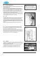
9.2.9 Flow switch
Disconnect the two pin connector and undo the two unions to release
the flow switch. Ensure that the two sealing rings and brass ring are not
damaged and are replaced with the new flow switch.
Note:
When replacing with new device, ensure arrow for flow on the
black body is pointing vertically upwards.
9.2.8 Pressure relief valve
Remove the plastic pipe from the safety discharge. Undo the pressure
sensor capillary and undo the union at the connection with the CH flow
pipe. Remove the pressure relief valve and inlet pipe. Remove the
plastic fitting from the discharge and undo the pipe connection to allow
removal of the valve. Fit replacement valve in reverse order using a
sealant suitable for potable water.
9.2.9 Pressure gauge sensor
Undo the pressure sensor capillary and unscrew the two posidrive
screws to release the cable clamp. Remove the gauge and capillary,
and replace.
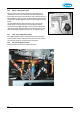
9.2.10 Pump head
Disconnect the pump wires from the controller (see note in § 9.2.1).
Undo two Allen bolts on the Wilo pump head (alternative pump Grundfos
has 4 Allen bolts) to remove the pump head from the body. Fit
replacement pump head in reverse order. The pump must be vented via
its vent plug after refilling the appliance.
9.2.11 Expansion vessel
Unscrew the flexible hose connection, making sure that the sealing ring
is not damaged. Unclip the bracket holding the vessel and fit
replacement including the sealing ring. Using the Schroeder valve on
the expansion vessel, and pump if required, check the pressure is 1 bar.
Note: The replacement of the components
below this box
requires the appliance
to be drained:-
CH side – Drain the appliance using the drain tap and drain the system at the lowest
point.
HW side – Close the valve for the cold water into the appliance and drain by
disconnecting the HW connections underneath the appliance or opening hot water taps.
After replacement, refill the appliance as given in §6.1.