
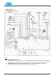
Technical data


52
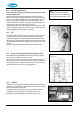
9.2.6 Burner / spark ignition probe
Remove the front cover of the heat exchanger as described in §9.1.2.
Unscrew the 4 screws shown on the photo to allow the stainless steel
burner mesh to be removed. These screws are Torx 20 (RVS A2 4,2x25”) or
Allen bolt M4x20 (units before 2006). The burner gasket should be checked
and replaced if damaged. Replace the burner mesh assembly and refit the
screws.
The spark ignition probe is shown in the photo in §9.1.2 and also the
diagram in §8.3. To replace the probe, pull off the ignition cable and
unscrew the 2 screws (Allen bolt M4x8). The seal should be checked and
replaced if damaged. Replace the probe and refit the seal and the screws.
Check the spark gap and replace the front cover, as described in §9.1.2.
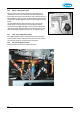
9.2.7 Flow / return temperature sensors
The supply temperature sensor is located above the return temperature
sensor. The latter is shown in the photo. Disconnect the two pin connector
and release the spring clip. Pull out the sensor and replace.
9.2.8 Hot water temperature sensor
Remove the electrical connector and replace the sensor.