
Technical data


49
Open the gas tap and check the gas couplings below the gas valve and on
the mounting bracket for leaks.
Switch on the electrical supply to the appliance
Switch on the appliance, using the On/Off button on the operating panel.
Check the front cover and the connection of the fan to the front cover for
leaks.
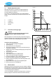
9.1.3 Checking the condensate discharge
See the diagram in §4.7.
Clean the condensate trap and the condensate discharge pipe.
After cleaning, fill the trap with water.
9.1.4 Inspect air supply / flue gas discharge system
Inspect the air supply / flue discharge system throughout its entirety,
ensuring that it is in sound condition with no damage to the pipes or joints.
Inspect the terminals ensuring that they are clear and unobstructed.
9.1.5 Checking the gas-air control
Check the gas-air control as given in §7.9, and adjust as necessary.
9.1.6 Check the CO/CO
2
ratio
The CO/CO2 ratio should be checked on each service. See §7.9 and §7.10
9.1.7 Completion of inspection and service
Check the pressure of the expansion vessel using a pump into the Schroeder
valve if necessary. With a pre charge pressure of 1 bar the pressure in the
expansion vessel should be equal to the CH system water pressure or at least
1 bar if the system pressure is lower than 1 bar.
Check the CH system water pressure shown on the display. This should be at
least 1 bar and at most 2 bar for a cold system. Top up the system if necessary.
Check the central heating system and the hot water supply for leaks and check
the boiler, controls and system for correct operation.
Check the corrosion inhibitor concentration level within the CH system,
topping up when necessary.
Refit the front panel and replace the screws at the bottom of the appliance.
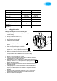
9.2 COMPONENT REPLACEMENT
9.2.1 Preparation
Switch off the appliance using the On/Off button on the operating panel.
Switch off the electrical supply to the appliance.
Close the gas tap.
Unscrew the two recessed screws left and right at the front underneath the
appliance and lift / remove the front panel. See photo in §4.5.3.
Wait until the appliance and the burner have cooled down.
Note – When removing cables / wires to the controller, the cable clamp must
be released first by unscrewing 2 posidrive screws and the controller hinged
down by unscrewing 2 posidrive screws as shown in diagram §5.3.
Note
After servicing, the Benchmark Checklist
and Service Record (located at the back
of this manual) must be completed and
signed and the manual left with the
customer.