
Technical data


42
according to the table below:-
Gas type
Natural gas H
Propane P
Gas category
2H G20
3P G31 (propane)
CO
2
% at low position (L)
(service and -)
8.8 – 9.2 9.3 – 9.7
CO
2
% at high position (H)
(service and +)
8.6 – 9.6 9.5 – 10.5
CO/CO
2
ratio
0.004 or less
0.004 or less
Gas inlet p
ressure dynamic (mBar)
17
-
25
25
-
45
Gas inlet pressure static (mBar)
20
37
Gas setting ring diameter (mm)
HE26
6.95
5.35
Gas setting ring diameter (mm)
HE40C
6.55
5.25
Minimum speed (% of max)
(parameter c)
25 40
Min. starting speed (% of max)
(parameter F)
70 50
Note: See also §7.3 (Parameters)
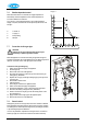
7.9 Setting gas-air control
Setting by measuring the CO
2
content of the flue gases
• A flue gas test point must be mounted right above the appliance in
the flue discharge.
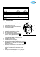
A. Dust cap (socket head wrench torx T15)
B. Setting screw for the low position (socket head wrench torx T15)
C. Off-set pressure measuring nipple
D. Inlet pressure measuring nipple
1. Switch off the appliance using the On/Off button (
-
on service
display).
2. Open the flue gas test point and insert the gas test probe.
3. Switch on the appliance using the On/Off button.
4. Set the boiler to the lowest output by simultaneously pressing the
“Service” and “–“ buttons on the operating panel until an
L
appears on the service display.
5. Measure the CO2 value and the CO/CO2 ratio. Check that these
correspond with the values in the table. If the CO2 value does not
correspond with the value in the table, proceed as follows for setting:
6. Remove the front cover of the appliance.
7. Remove the dust cap (A) with a torx T15 driver
8. Using a torx driver (T15), adjust the setting screw (B) to the correct CO
2
value
(clockwise higher and counter-clockwise lower).
9. After measuring and setting, set the boiler to the highest output by simultaneously
pressing the “Service” and “+“ buttons (twice) on the operating panel until an
H
appears on the service display.
10.
Measure the CO2 value and the CO/CO2 ratio. Check that these correspond with
the values in the table.
11.
If the high output CO
2
is not within the parameters allowed in the chart above,
return to low output and adjust the CO2 setting at low output before returning to
high out put to check it again. Contact the manufacturer if you encounter
difficulties.
12. Exit the test mode by simultaneously pressing the “+” and “–“ buttons on the
operating panel. Replace the dust cap (A) and close the flue gas test point.
13. Remount the front cover of the appliance.
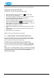
Siemens gas valve & ignition transformer