
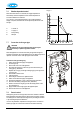
Technical data


50
9.2.2 Gas valve/ ignition block
Note: The gas valve is factory-preset and therefore only Atmos or their
agents can supply these.
Remove the spark ignition block by pulling apart horizontally. Undo the
upper and lower unions, making sure that the ‘O’ rings and gas setting ring
are not lost or damaged (see diagram in §7.7). Replace the gas valve, and
refit the ‘O’ rings, the gas setting ring, the unions and the ignition block.
Note: After replacing the gas valve, carry out the gas analysis adjustments
and the CO/CO2 ratio check as given in §7.9 and §7.10.
If replacing the ignition block, then pull apart as above. Remove the push-fit
cable to the probe and undo the X1 connections at the controller and earth.
Replace the ignition block and make the connections.
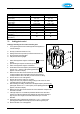
9.2.3 Fan
Remove the electrical connector. Undo the upper union from the gas valve.
Undo the two 8mm nuts as shown in the photo. Remove the assembly
including the sealing ring. Undo the three Allen screws (M4x10) to remove
the gas inlet sub assembly. Fit the replacement fan in reverse order. Check
the sealing ring is not damaged and replace if necessary; check that it seals
correctly.
See also §9.2.4 below for appliances fitted with Non Return Valve (flue
gas).
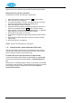
9.2.4 Note for CFS systems with Non Return Valve (flue gas)
When refitting the fan, the NRV MUST be refitted (see diagram). Fold the
silicon valve (1) of the NRV carefully into a U-form.
Place the valve + holder (1+2) into the hole of the front plate, making sure
the valve is placed in the correct position (direction toward the front plate as
shown).Replace the fan + seal back on the front plate, and screw both nuts
(4) tight, making sure the valve stays in the right position.
9.2.5 Controller
If possible, record the parameter settings as described in §7.3. Remove the
display cover and undo the two posidrive screws to drop down the controller
panel as shown in the diagram in §5.3.
Pull apart the connectors and undo the 8mm nut to allow the controller
assembly to be removed and replaced. After replacement, set the required
parameter settings as described in §7.2and §7.3,
Note
The ignition block is held on the gas valve
by a Torx T10 screw. Remove this screw
prior to pulling the ignition unit off.