
Corp. SpaceWire Router User Manual

Ref.:
UoD_SpW-10X_
UserManual
Issue:
3.4
SpW-10X
SpaceWire Router
User Manual
Date:
11
th
July 2008
Preliminary
31
5. DEVICE INTERFACE
The device pins used by each interface are described in this section. There is a table for each type of
interface listing the signals in that interface. These tables have the following fields:
Pin No: The device pin number
Signal: The name of the signal
Dir: The direction of the signal; in, out or in/out
Description: An explanation of what the signal does.
Type: The type of signal
The sections below define the pin out of the SpaceWire router. Its interfaces are split into several
types, separated by headings for clarity:
5.1 Global signals: clock and reset
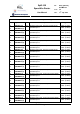
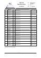
5.2 SpaceWire interface signals
5.3 External port signals
5.4 Time-code interface signals
5.5 Configuration signals
5.6 Reset configuration signals
5.7 Power and Ground
The following signal types are used in the SpaceWire Router:
CMOS3V3 3.3 Volt CMOS logic
LVDS Low Voltage Differential Signal
3V3 3.3 Volt power
GND Ground
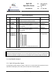
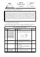
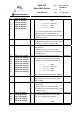
5.1 GLOBAL SIGNALS
The global system clock and reset signals are listed in Table 5-1.