
Corp. SpaceWire Router User Manual


Ref.:
UoD_SpW-10X_
UserManual
Issue:
3.4
SpW-10X
SpaceWire Router
User Manual
Date:
11
th
July 2008
Preliminary
25
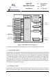
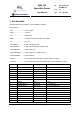
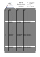
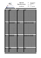
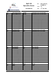
4. PIN LOCATIONS
The SpaceWire router package is a 196 pin MQFPF package.
Type definition:
- 3V3.................................3.3 Volt power
- GND................................Ground
- PIC................................ CMOS input
- PRD4............................ pull-down resistor (min.16kΩ, max. 80kΩ)
- PLL ............................... PLL pins
- PFILVDSZP.................. LVDS cold sparing input
- PFILVDSZPB ............... LVDS cold sparing input, negative input
- PFOLVDS33ZP ............ LVDS output 3.3V
- PFOLVDS33ZPB.......... LVDS output 3.3V, negative output
- PFOLVDSREFZ ........... LVDS reference
- PO44F .......................... 4x driving strength output (fast, minimum slew rate control)
- PO22F-tri...................... 2x driving strength output with tristate (fast, minimum slew rate control)
Pin Signal Type Description
1 VDDB 3V3 Power
2 CLK PIC System clock
3 RSTN PIC Reset
4 TestIOEn PIC PRD4 Chip test pin
5 TestEn PIC PRD4 Chip test pin
6 FEEDBDIV(0) PIC PRD4 PLL divider bit 0 (LS)
7 VSSA1 GND Ground
8 VDDA1 3V3 Power
9 FEEDBDIV(1) PIC PRD4 PLL divider bit 1
10 FEEDBDIV(2) PIC PRD4 PLL divider bit 2 (MS)
11 VSSB GND Ground
12 VDDPLL PLL PLL power
13 VCOBias PLL PLL VCO bias
14 LoopFilter PLL PLL loop filter
15 VSSPLL PLL PLL ground
16 VDDB 3V3 Power
17 DINPlus(1) PFILVDSZP SpW port 1 input data +