
Corp. SpaceWire Router User Manual


Ref.:
UoD_SpW-10X_
UserManual
Issue:
3.4
SpW-10X
SpaceWire Router
User Manual
Date:
11
th
July 2008
Preliminary
22
External Port
Output FIFO
Input FIFO
Crossbar
Switch
Control
Logic
Routing
Table
Time-Code
Interface
Configuration
Port
Status/Error
Registers
SpaceWire
Port 1
SpaceWire
Port 2
SpaceWire
Port 3
SpaceWire
Port 4
SpaceWire
Port 5
SpaceWire
Port 6
SpaceWire
Port 7
Control
Registers
SpaceWire
Port 8
SpaceWire
Interfaces
External
Input/Outp ut
Status
Outputs
Time-Code
Inputs /
Outputs
External Port
Output FIFO
Input FIFOExternal
Input/Outp ut
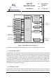
Figure 3-1 SpaceWire router block diagram
The following paragraphs define the SpaceWire router functional logic blocks in more detail.
3.1 SPACEWIRE PORTS
The SpaceWire router has eight bi-directional SpaceWire links each conformant with the SpaceWire
standard. Each SpaceWire link is controlled by an associated link register and routing control logic.
Network level error recovery is performed when an error is detected on the SpaceWire link as defined
in the SpaceWire standard. Packets received on SpaceWire links are routed by the routing control
logic to the configuration port, other SpaceWire link ports or the external FIFO ports. Packets with
invalid addresses are discarded by the SpaceWire router dependent on the packet address. The
SpaceWire link status is recorded in the associated link register and error status is held by the router
until cleared by a configuration command.
3.2 EXTERNAL PORTS
The SpaceWire router has two bi-directional parallel FIFO interfaces that can be used to connect the
router to an external host system. The external port FIFO is two data characters deep. Each FIFO is