
Corp. SpaceWire Router User Manual

Ref.:
UoD_SpW-10X_
UserManual
Issue:
3.4
SpW-10X
SpaceWire Router
User Manual
Date:
11
th
July 2008
Preliminary
128
10. SWITCHING CHARACTERISTICS
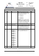
10.1 CLOCK AND RESET TIMING PARAMETERS
The global clock and asynchronous reset timing parameters are listed below.
Table 10-1 Clock and reset timing parameters
Description Symbol Value Units
Clock period minimum value T
CL
31.7
(1)
(TBC)
ns, min
Clock period maximum value T
CH
35
(2)
(TBC)
ns, max
Clock minimum pulse width T
ACLK
5 ns, min
Clock input jitter T
CJITTER
+/- 2 ns, max
PLL lock time after reset T
PLLLOCK
20 µs, max
Reset minimum pulse width T
ARST
5 ns, min
Reset end till operational T
RST2OP
20 ns, max
(1) The PLL max. frequency is 200 MHz+TBD MHz.
(2) The PLL min. frequency is 100 MHz-TBD MHz.
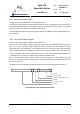
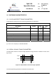
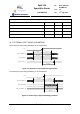
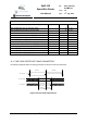
10.2 SERIAL SIGNALS TIMING PARAMETERS
The data strobe minimum consecutive edge separation timing parameter is defined as shown in the
figure below.
DIN(n)
SIN(n)
T
DSINS
T
DSINS
Figure 10-1 DS minimum consecutive edge separation
The serial signal timing parameters are defined in the table below.