
Datasheet
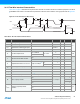
Table Of Contents
- Features
- 1. Ordering Information
- 2. Typical Applications
- 3. Pinout and Block Diagram
- 4. Overview
- 5. Resources
- 6. Capacitive Touch Sensing
- 7. CPU
- 8. Memories
- 9. EDMA – Enhanced DMA Controller
- 10. Event System
- 11. System Clock and Clock options
- 11.1 Features
- 11.2 Overview
- 11.3 Clock Sources
- 11.3.1 32kHz Ultra Low Power Internal Oscillator
- 11.3.2 32.768kHz Calibrated Internal Oscillator
- 11.3.3 32.768kHz Crystal Oscillator
- 11.3.4 0.4 - 16MHz Crystal Oscillator
- 11.3.5 8MHz Calibrated Internal Oscillator
- 11.3.6 32MHz Run-time Calibrated Internal Oscillator
- 11.3.7 External Clock Sources
- 11.3.8 PLL with 1x-31x Multiplication Factor
- 12. Power Management and Sleep Modes
- 13. System Control and Reset
- 14. WDT – Watchdog Timer
- 15. Interrupts and Programmable Multilevel Interrupt Controller
- 16. I/O Ports
- 17. Timer Counter Type 4 and 5
- 18. WeX – Waveform Extension
- 19. Hi-Res – High Resolution Extension
- 20. Fault Extension
- 21. RTC – 16-bit Real-Time Counter
- 22. TWI – Two-Wire Interface
- 23. SPI – Serial Peripheral Interface
- 24. USART
- 25. IRCOM – IR Communication Module
- 26. XCL – XMEGA Custom Logic Module
- 27. CRC – Cyclic Redundancy Check Generator
- 28. ADC – 12-bit Analog to Digital Converter
- 29. DAC – Digital to Analog Converter
- 30. AC – Analog Comparator
- 31. Programming and Debugging
- 32. Pinout and Pin Functions
- 33. Peripheral Module Address Map
- 34. Instruction Set Summary
- 35. Packaging Information
- 36. Electrical Characteristics
- 36.1 Absolute Maximum Ratings
- 36.2 General Operating Ratings
- 36.3 Current Consumption
- 36.4 Wake-up Time from Sleep Modes
- 36.5 I/O Pin Characteristics
- 36.6 ADC Characteristics
- 36.7 DAC Characteristics
- 36.8 Analog Comparator Characteristics
- 36.9 Bandgap and Internal 1.0V Reference Characteristics
- 36.10 External Reset Characteristics
- 36.11 Power-on Reset Characteristics
- 36.12 Flash and EEPROM Characteristics
- 36.13 Clock and Oscillator Characteristics
- 36.13.1 Calibrated 32.768kHz Internal Oscillator Characteristics
- 36.13.2 Calibrated 8MHz Internal Oscillator Characteristics
- 36.13.3 Calibrated and Tunable 32MHz Internal Oscillator Characteristics
- 36.13.4 32 kHz Internal ULP Oscillator Characteristics
- 36.13.5 Internal Phase Locked Loop (PLL) Characteristics
- 36.13.6 External Clock Characteristics
- 36.13.7 External 16MHz Crystal Oscillator and XOSC Characteristics
- 36.13.8 External 32.768kHz Crystal Oscillator and TOSC Characteristics
- 36.14 SPI Characteristics
- 36.15 Two-Wire Interface Characteristics
- 37. Typical Characteristics
- 37.1 Current Consumption
- 37.2 I/O Pin Characteristics
- 37.3 ADC Characteristics
- 37.4 DAC Characteristics
- 37.5 AC Characteristics
- 37.6 Internal 1.0V Reference Characteristics
- 37.7 BOD Characteristics
- 37.8 External Reset Characteristics
- 37.9 Power-on Reset Characteristics
- 37.10 Oscillator Characteristics
- 37.11 Two-wire Interface Characteristics
- 37.12 PDI Characteristics
- 38. Errata – ATxmega32E5 / ATxmega16E5 / ATxmega8E5
- 39. Revision History
- Table of Contents
91
XMEGA E5 [DATASHEET]
Atmel-8153J–AVR-ATxmega8E5-ATxmega16E5-ATxmega32E5_Datasheet–11/2014
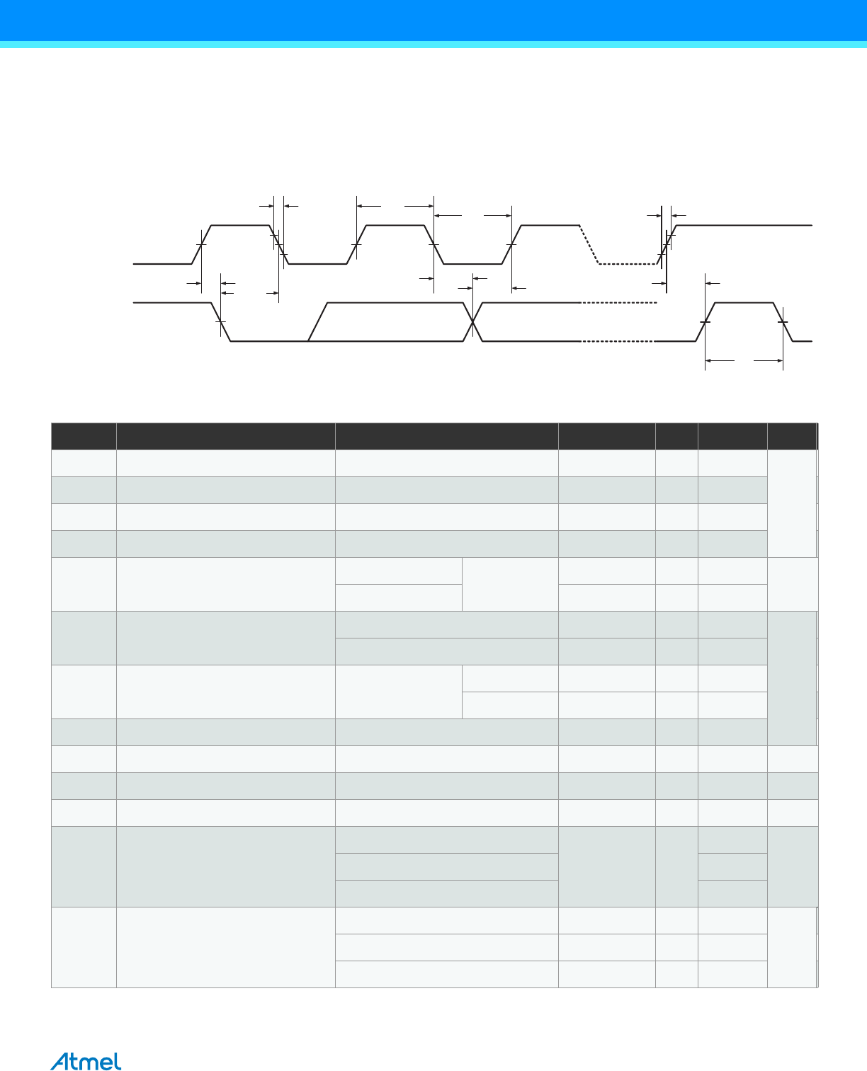
36.15 Two-Wire Interface Characteristics
Table 36-6 on page 76 describes the requirements for devices connected to the two-wire interface (TWI) Bus. The Atmel
AVR XMEGA TWI meets or exceeds these requirements under the noted conditions. Timing symbols refer to Figure 36-
7.
Figure 36-7. Two-wire Interface Bus Timing
Table 36-30. Two-wire Interface Characteristics
t
HD;STA
t
of
SDA
SCL
t
LOW
t
HIGH
t
SU;STA
t
BUF
t
r
t
HD;DAT
t
SU;DAT
t
SU;STO
Symbol Parameter Condition Min. Typ. Max. Units
V
IH
Input high voltage 0.7V
CC
V
CC
+0.5
V
V
IL
Input low voltage -0.5 0.3V
CC
V
hys
Hysteresis of Schmitt trigger inputs 0.05V
CC
(1)
V
OL
Output low voltage 3mA, sink current 0 0.4
I
OL
Low level output current
f
SCL
≤ 400kHz
V
OL
= 0.4V
3
mA
f
SCL
≤ 1MHz 20
t
r
Rise time for both SDA and SCL
f
SCL
≤ 400kHz 20+0.1C
b
(1)(2)
300
ns
f
SCL
≤ 1MHz 120
t
of
Output fall time from V
IHmin
to V
ILmax
10pF< C
b
<400pF
(2)
f
SCL
≤ 400kHz 20+0.1C
b
(1)(2)
250
f
SCL
≤ 1MHz 120
t
SP
Spikes suppressed by Input filter 0 50
I
I
Input current for each I/O Pin 0.1 V
CC
<V
I
<0.9 V
CC
-10 10 µA
C
I
Capacitance for each I/O Pin 10 pF
f
SCL
SCL clock frequency f
PER
(3)
> max(10f
SCL
,250kHz) 0 1 MHz
R
P
Value of pull-up resistor
f
SCL
≤ 100kHz
(V
CC
-0.4V)/I
OL
100ns/C
b
Ωf
SCL
≤ 400kHz 300ns/C
b
f
SCL
≤ 1MHz 550ns/C
b
t
HD;STA
Hold time (repeated) START
condition
f
SCL
≤ 100kHz 4
µsf
SCL
≤ 400kHz 0.6
f
SCL
≤ 1MHz 0.26