
Datasheet
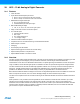
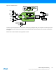
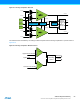
Table Of Contents
- Features
- 1. Ordering Information
- 2. Typical Applications
- 3. Pinout and Block Diagram
- 4. Overview
- 5. Resources
- 6. Capacitive Touch Sensing
- 7. CPU
- 8. Memories
- 9. EDMA – Enhanced DMA Controller
- 10. Event System
- 11. System Clock and Clock options
- 11.1 Features
- 11.2 Overview
- 11.3 Clock Sources
- 11.3.1 32kHz Ultra Low Power Internal Oscillator
- 11.3.2 32.768kHz Calibrated Internal Oscillator
- 11.3.3 32.768kHz Crystal Oscillator
- 11.3.4 0.4 - 16MHz Crystal Oscillator
- 11.3.5 8MHz Calibrated Internal Oscillator
- 11.3.6 32MHz Run-time Calibrated Internal Oscillator
- 11.3.7 External Clock Sources
- 11.3.8 PLL with 1x-31x Multiplication Factor
- 12. Power Management and Sleep Modes
- 13. System Control and Reset
- 14. WDT – Watchdog Timer
- 15. Interrupts and Programmable Multilevel Interrupt Controller
- 16. I/O Ports
- 17. Timer Counter Type 4 and 5
- 18. WeX – Waveform Extension
- 19. Hi-Res – High Resolution Extension
- 20. Fault Extension
- 21. RTC – 16-bit Real-Time Counter
- 22. TWI – Two-Wire Interface
- 23. SPI – Serial Peripheral Interface
- 24. USART
- 25. IRCOM – IR Communication Module
- 26. XCL – XMEGA Custom Logic Module
- 27. CRC – Cyclic Redundancy Check Generator
- 28. ADC – 12-bit Analog to Digital Converter
- 29. DAC – Digital to Analog Converter
- 30. AC – Analog Comparator
- 31. Programming and Debugging
- 32. Pinout and Pin Functions
- 33. Peripheral Module Address Map
- 34. Instruction Set Summary
- 35. Packaging Information
- 36. Electrical Characteristics
- 36.1 Absolute Maximum Ratings
- 36.2 General Operating Ratings
- 36.3 Current Consumption
- 36.4 Wake-up Time from Sleep Modes
- 36.5 I/O Pin Characteristics
- 36.6 ADC Characteristics
- 36.7 DAC Characteristics
- 36.8 Analog Comparator Characteristics
- 36.9 Bandgap and Internal 1.0V Reference Characteristics
- 36.10 External Reset Characteristics
- 36.11 Power-on Reset Characteristics
- 36.12 Flash and EEPROM Characteristics
- 36.13 Clock and Oscillator Characteristics
- 36.13.1 Calibrated 32.768kHz Internal Oscillator Characteristics
- 36.13.2 Calibrated 8MHz Internal Oscillator Characteristics
- 36.13.3 Calibrated and Tunable 32MHz Internal Oscillator Characteristics
- 36.13.4 32 kHz Internal ULP Oscillator Characteristics
- 36.13.5 Internal Phase Locked Loop (PLL) Characteristics
- 36.13.6 External Clock Characteristics
- 36.13.7 External 16MHz Crystal Oscillator and XOSC Characteristics
- 36.13.8 External 32.768kHz Crystal Oscillator and TOSC Characteristics
- 36.14 SPI Characteristics
- 36.15 Two-Wire Interface Characteristics
- 37. Typical Characteristics
- 37.1 Current Consumption
- 37.2 I/O Pin Characteristics
- 37.3 ADC Characteristics
- 37.4 DAC Characteristics
- 37.5 AC Characteristics
- 37.6 Internal 1.0V Reference Characteristics
- 37.7 BOD Characteristics
- 37.8 External Reset Characteristics
- 37.9 Power-on Reset Characteristics
- 37.10 Oscillator Characteristics
- 37.11 Two-wire Interface Characteristics
- 37.12 PDI Characteristics
- 38. Errata – ATxmega32E5 / ATxmega16E5 / ATxmega8E5
- 39. Revision History
- Table of Contents
53
XMEGA E5 [DATASHEET]
Atmel-8153J–AVR-ATxmega8E5-ATxmega16E5-ATxmega32E5_Datasheet–11/2014
29. DAC – Digital to Analog Converter
29.1 Features
One Digital to Analog Converter (DAC)
12-bit resolution
Two independent, continuous-drive output channels
Up to 1 million samples per second conversion rate per DAC channel
Built-in calibration that removes:
Offset error
Gain error
Multiple conversion trigger sources
On new available data
Events from the event system
Drive capabilities and support for
Resistive loads
Capacitive loads
Combined resistive and capacitive loads
Internal and external reference options
DAC output available as input to analog comparator and ADC
Low-power mode, with reduced drive strength
Optional EDMA transfer of data
29.2 Overview
The digital-to-analog converter (DAC) converts digital values to voltages. The DAC has two channels, each with 12-bit
resolution, and is capable of converting up to one million samples per second (Msps) on each channel. The built-in
calibration system can remove offset and gain error when loaded with calibration values from software.
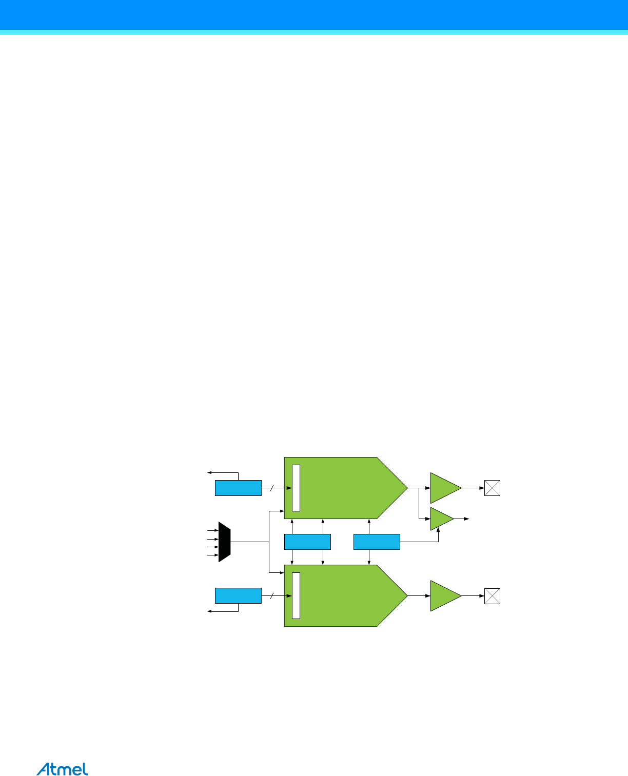
Figure 29-1. DAC Overview
A DAC conversion is automatically started when new data to be converted are available. Events from the event system
can also be used to trigger a conversion, and this enables synchronized and timed conversions between the DAC and
other peripherals, such as a timer/counter. The EDMA controller can be used to transfer data to the DAC.
The DAC is capable of driving both resistive and capacitive loads aswell as loads which combine both. A low-power
mode is available, which will reduce the drive strength of the output. Internal and external voltage references can be
used. The DAC output is also internally available for use as input to the analog comparator or ADC.
PORTA has one DAC. Notation of this peripheral is DACA.
DAC0
DAC1
CTRLA
CH1DATA
CH0DATA
Trigger
Trigger
Internal Output
enable
Enable
Internal 1.00V
AREFA
Reference
selection
AVCC
Output
Driver
Output
Driver
D
A
T
A
Int.
driver
D
A
T
A
CTRLB
EDMA req
(Data Empty)
EDMA req
(Data Empty)
Select
12
12
Select
Enable
To
AC/ADC
AREFD