
Datasheet
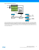

Table Of Contents
- Features
- 1. Ordering Information
- 2. Typical Applications
- 3. Pinout and Block Diagram
- 4. Overview
- 5. Resources
- 6. Capacitive Touch Sensing
- 7. CPU
- 8. Memories
- 9. EDMA – Enhanced DMA Controller
- 10. Event System
- 11. System Clock and Clock options
- 11.1 Features
- 11.2 Overview
- 11.3 Clock Sources
- 11.3.1 32kHz Ultra Low Power Internal Oscillator
- 11.3.2 32.768kHz Calibrated Internal Oscillator
- 11.3.3 32.768kHz Crystal Oscillator
- 11.3.4 0.4 - 16MHz Crystal Oscillator
- 11.3.5 8MHz Calibrated Internal Oscillator
- 11.3.6 32MHz Run-time Calibrated Internal Oscillator
- 11.3.7 External Clock Sources
- 11.3.8 PLL with 1x-31x Multiplication Factor
- 12. Power Management and Sleep Modes
- 13. System Control and Reset
- 14. WDT – Watchdog Timer
- 15. Interrupts and Programmable Multilevel Interrupt Controller
- 16. I/O Ports
- 17. Timer Counter Type 4 and 5
- 18. WeX – Waveform Extension
- 19. Hi-Res – High Resolution Extension
- 20. Fault Extension
- 21. RTC – 16-bit Real-Time Counter
- 22. TWI – Two-Wire Interface
- 23. SPI – Serial Peripheral Interface
- 24. USART
- 25. IRCOM – IR Communication Module
- 26. XCL – XMEGA Custom Logic Module
- 27. CRC – Cyclic Redundancy Check Generator
- 28. ADC – 12-bit Analog to Digital Converter
- 29. DAC – Digital to Analog Converter
- 30. AC – Analog Comparator
- 31. Programming and Debugging
- 32. Pinout and Pin Functions
- 33. Peripheral Module Address Map
- 34. Instruction Set Summary
- 35. Packaging Information
- 36. Electrical Characteristics
- 36.1 Absolute Maximum Ratings
- 36.2 General Operating Ratings
- 36.3 Current Consumption
- 36.4 Wake-up Time from Sleep Modes
- 36.5 I/O Pin Characteristics
- 36.6 ADC Characteristics
- 36.7 DAC Characteristics
- 36.8 Analog Comparator Characteristics
- 36.9 Bandgap and Internal 1.0V Reference Characteristics
- 36.10 External Reset Characteristics
- 36.11 Power-on Reset Characteristics
- 36.12 Flash and EEPROM Characteristics
- 36.13 Clock and Oscillator Characteristics
- 36.13.1 Calibrated 32.768kHz Internal Oscillator Characteristics
- 36.13.2 Calibrated 8MHz Internal Oscillator Characteristics
- 36.13.3 Calibrated and Tunable 32MHz Internal Oscillator Characteristics
- 36.13.4 32 kHz Internal ULP Oscillator Characteristics
- 36.13.5 Internal Phase Locked Loop (PLL) Characteristics
- 36.13.6 External Clock Characteristics
- 36.13.7 External 16MHz Crystal Oscillator and XOSC Characteristics
- 36.13.8 External 32.768kHz Crystal Oscillator and TOSC Characteristics
- 36.14 SPI Characteristics
- 36.15 Two-Wire Interface Characteristics
- 37. Typical Characteristics
- 37.1 Current Consumption
- 37.2 I/O Pin Characteristics
- 37.3 ADC Characteristics
- 37.4 DAC Characteristics
- 37.5 AC Characteristics
- 37.6 Internal 1.0V Reference Characteristics
- 37.7 BOD Characteristics
- 37.8 External Reset Characteristics
- 37.9 Power-on Reset Characteristics
- 37.10 Oscillator Characteristics
- 37.11 Two-wire Interface Characteristics
- 37.12 PDI Characteristics
- 38. Errata – ATxmega32E5 / ATxmega16E5 / ATxmega8E5
- 39. Revision History
- Table of Contents

50
XMEGA E5 [DATASHEET]
Atmel-8153J–AVR-ATxmega8E5-ATxmega16E5-ATxmega32E5_Datasheet–11/2014
27. CRC – Cyclic Redundancy Check Generator
27.1 Features
Cyclic redundancy check (CRC) generation and checking for
Communication data
Program or data in flash memory
Data in SRAM and I/O memory space
Integrated with flash memory, EDMA controller, and CPU
Continuous CRC on data going through an EDMA channel
Automatic CRC of the complete or a selectable range of the flash memory
CPU can load data to the CRC generator through the I/O interface
CRC polynomial software selectable to:
CRC-16 (CRC-CCITT)
CRC-32 (IEEE 802.3)
Zero remainder detection
27.2 Overview
A cyclic redundancy check (CRC) is an error detection technique test algorithm used to find accidental errors in data, and
it is commonly used to determine the correctness of a data transmission, and data present in the data and program
memories. A CRC takes a data stream or a block of data as input and generates a 16- or 32-bit output that can be
appended to the data and used as a checksum. When the same data are later received or read, the device or application
repeats the calculation. If the new CRC result does not match the one calculated earlier, the block contains a data error.
The application will then detect this and may take a corrective action, such as requesting the data to be sent again or
simply not using the incorrect data.
Typically, an n-bit CRC applied to a data block of arbitrary length will detect any single error burst not longer than n bits
(any single alteration that spans no more than n bits of the data), and will detect the fraction 1-2
-n
of all longer error
bursts. The CRC module in XMEGA devices supports two commonly used CRC polynomials; CRC-16 (CRC-CCITT) and
CRC-32 (IEEE 802.3).
CRC-16:
Polynomial: x
16
+ x
12
+ x
5
+ 1
Hex Value: 0x1021
CRC-32:
Polynomial: x
32
+ x
26
+ x
23
+ x
22
+ x
16
+ x
12
+ x
11
+ x
10
+ x
8
+ x
7
+ x
5
+ x
4
+ x
2
+ x + 1
Hex Value: 0x04C11DB7