
Datasheet
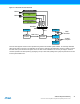

Table Of Contents
- Features
- 1. Ordering Information
- 2. Typical Applications
- 3. Pinout and Block Diagram
- 4. Overview
- 5. Resources
- 6. Capacitive Touch Sensing
- 7. CPU
- 8. Memories
- 9. EDMA – Enhanced DMA Controller
- 10. Event System
- 11. System Clock and Clock options
- 11.1 Features
- 11.2 Overview
- 11.3 Clock Sources
- 11.3.1 32kHz Ultra Low Power Internal Oscillator
- 11.3.2 32.768kHz Calibrated Internal Oscillator
- 11.3.3 32.768kHz Crystal Oscillator
- 11.3.4 0.4 - 16MHz Crystal Oscillator
- 11.3.5 8MHz Calibrated Internal Oscillator
- 11.3.6 32MHz Run-time Calibrated Internal Oscillator
- 11.3.7 External Clock Sources
- 11.3.8 PLL with 1x-31x Multiplication Factor
- 12. Power Management and Sleep Modes
- 13. System Control and Reset
- 14. WDT – Watchdog Timer
- 15. Interrupts and Programmable Multilevel Interrupt Controller
- 16. I/O Ports
- 17. Timer Counter Type 4 and 5
- 18. WeX – Waveform Extension
- 19. Hi-Res – High Resolution Extension
- 20. Fault Extension
- 21. RTC – 16-bit Real-Time Counter
- 22. TWI – Two-Wire Interface
- 23. SPI – Serial Peripheral Interface
- 24. USART
- 25. IRCOM – IR Communication Module
- 26. XCL – XMEGA Custom Logic Module
- 27. CRC – Cyclic Redundancy Check Generator
- 28. ADC – 12-bit Analog to Digital Converter
- 29. DAC – Digital to Analog Converter
- 30. AC – Analog Comparator
- 31. Programming and Debugging
- 32. Pinout and Pin Functions
- 33. Peripheral Module Address Map
- 34. Instruction Set Summary
- 35. Packaging Information
- 36. Electrical Characteristics
- 36.1 Absolute Maximum Ratings
- 36.2 General Operating Ratings
- 36.3 Current Consumption
- 36.4 Wake-up Time from Sleep Modes
- 36.5 I/O Pin Characteristics
- 36.6 ADC Characteristics
- 36.7 DAC Characteristics
- 36.8 Analog Comparator Characteristics
- 36.9 Bandgap and Internal 1.0V Reference Characteristics
- 36.10 External Reset Characteristics
- 36.11 Power-on Reset Characteristics
- 36.12 Flash and EEPROM Characteristics
- 36.13 Clock and Oscillator Characteristics
- 36.13.1 Calibrated 32.768kHz Internal Oscillator Characteristics
- 36.13.2 Calibrated 8MHz Internal Oscillator Characteristics
- 36.13.3 Calibrated and Tunable 32MHz Internal Oscillator Characteristics
- 36.13.4 32 kHz Internal ULP Oscillator Characteristics
- 36.13.5 Internal Phase Locked Loop (PLL) Characteristics
- 36.13.6 External Clock Characteristics
- 36.13.7 External 16MHz Crystal Oscillator and XOSC Characteristics
- 36.13.8 External 32.768kHz Crystal Oscillator and TOSC Characteristics
- 36.14 SPI Characteristics
- 36.15 Two-Wire Interface Characteristics
- 37. Typical Characteristics
- 37.1 Current Consumption
- 37.2 I/O Pin Characteristics
- 37.3 ADC Characteristics
- 37.4 DAC Characteristics
- 37.5 AC Characteristics
- 37.6 Internal 1.0V Reference Characteristics
- 37.7 BOD Characteristics
- 37.8 External Reset Characteristics
- 37.9 Power-on Reset Characteristics
- 37.10 Oscillator Characteristics
- 37.11 Two-wire Interface Characteristics
- 37.12 PDI Characteristics
- 38. Errata – ATxmega32E5 / ATxmega16E5 / ATxmega8E5
- 39. Revision History
- Table of Contents

45
XMEGA E5 [DATASHEET]
Atmel-8153J–AVR-ATxmega8E5-ATxmega16E5-ATxmega32E5_Datasheet–11/2014
24. USART
24.1 Features
Two identical USART peripherals
Full-duplex or one-wire half-duplex operation
Asynchronous or synchronous operation
Synchronous clock rates up to 1/2 of the device clock frequency
Asynchronous clock rates up to 1/8 of the device clock frequency
Supports serial frames with:
5, 6, 7, 8, or 9 data bits
Optionally even and odd parity bits
1 or 2 stop bits
Fractional baud rate generator
Can generate desired baud rate from any system clock frequency
No need for external oscillator with certain frequencies
Built-in error detection and correction schemes
Odd or even parity generation and parity check
Data overrun and framing error detection
Noise filtering includes false start bit detection and digital low-pass filter
Separate interrupts for
Transmit complete
Transmit data register empty
Receive complete
Multiprocessor communication mode
Addressing scheme to address a specific devices on a multidevice bus
Enable unaddressed devices to automatically ignore all frames
System wake-up from Start bit
Master SPI mode
Double buffered operation
Configurable data order
Operation up to 1/2 of the peripheral clock frequency
IRCOM module for IrDA compliant pulse modulation/demodulation
One USART is connected to XMEGA Custom Logic (XCL) module:
Extend serial frame length up to 256 bit by using the peripheral counter
Modulate/demodulate data within the frame by using the glue logic outputs
24.2 Overview
The universal synchronous and asynchronous serial receiver and transmitter (USART) is a fast and flexible serial
communication module. The USART supports full-duplex with asynchronous and synchronous operation and single wire
half-duplex communication with asynchronous operation. The USART can be configured to operate in SPI master mode
and used for SPI communication.
Communication is frame based, and the frame format can be customized to support a wide range of standards. The
USART is buffered in both directions, enabling continued data transmission without any delay between frames. Separate
interrupts for receive and transmit complete enable fully interrupt driven communication. Frame error and buffer overflow
are detected in hardware and indicated with separate status flags. Even or odd parity generation and parity check can
also be enabled.
In one-wire configuration, the TxD pin is connected to the RxD pin internally, limiting the IO pins usage. If the receiver is
enabled when transmitting, it will receive what the transmitter is sending. This mode can be used for bit error detection.