
Datasheet
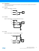
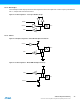
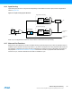
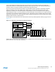
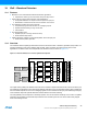

Table Of Contents
- Features
- 1. Ordering Information
- 2. Typical Applications
- 3. Pinout and Block Diagram
- 4. Overview
- 5. Resources
- 6. Capacitive Touch Sensing
- 7. CPU
- 8. Memories
- 9. EDMA – Enhanced DMA Controller
- 10. Event System
- 11. System Clock and Clock options
- 11.1 Features
- 11.2 Overview
- 11.3 Clock Sources
- 11.3.1 32kHz Ultra Low Power Internal Oscillator
- 11.3.2 32.768kHz Calibrated Internal Oscillator
- 11.3.3 32.768kHz Crystal Oscillator
- 11.3.4 0.4 - 16MHz Crystal Oscillator
- 11.3.5 8MHz Calibrated Internal Oscillator
- 11.3.6 32MHz Run-time Calibrated Internal Oscillator
- 11.3.7 External Clock Sources
- 11.3.8 PLL with 1x-31x Multiplication Factor
- 12. Power Management and Sleep Modes
- 13. System Control and Reset
- 14. WDT – Watchdog Timer
- 15. Interrupts and Programmable Multilevel Interrupt Controller
- 16. I/O Ports
- 17. Timer Counter Type 4 and 5
- 18. WeX – Waveform Extension
- 19. Hi-Res – High Resolution Extension
- 20. Fault Extension
- 21. RTC – 16-bit Real-Time Counter
- 22. TWI – Two-Wire Interface
- 23. SPI – Serial Peripheral Interface
- 24. USART
- 25. IRCOM – IR Communication Module
- 26. XCL – XMEGA Custom Logic Module
- 27. CRC – Cyclic Redundancy Check Generator
- 28. ADC – 12-bit Analog to Digital Converter
- 29. DAC – Digital to Analog Converter
- 30. AC – Analog Comparator
- 31. Programming and Debugging
- 32. Pinout and Pin Functions
- 33. Peripheral Module Address Map
- 34. Instruction Set Summary
- 35. Packaging Information
- 36. Electrical Characteristics
- 36.1 Absolute Maximum Ratings
- 36.2 General Operating Ratings
- 36.3 Current Consumption
- 36.4 Wake-up Time from Sleep Modes
- 36.5 I/O Pin Characteristics
- 36.6 ADC Characteristics
- 36.7 DAC Characteristics
- 36.8 Analog Comparator Characteristics
- 36.9 Bandgap and Internal 1.0V Reference Characteristics
- 36.10 External Reset Characteristics
- 36.11 Power-on Reset Characteristics
- 36.12 Flash and EEPROM Characteristics
- 36.13 Clock and Oscillator Characteristics
- 36.13.1 Calibrated 32.768kHz Internal Oscillator Characteristics
- 36.13.2 Calibrated 8MHz Internal Oscillator Characteristics
- 36.13.3 Calibrated and Tunable 32MHz Internal Oscillator Characteristics
- 36.13.4 32 kHz Internal ULP Oscillator Characteristics
- 36.13.5 Internal Phase Locked Loop (PLL) Characteristics
- 36.13.6 External Clock Characteristics
- 36.13.7 External 16MHz Crystal Oscillator and XOSC Characteristics
- 36.13.8 External 32.768kHz Crystal Oscillator and TOSC Characteristics
- 36.14 SPI Characteristics
- 36.15 Two-Wire Interface Characteristics
- 37. Typical Characteristics
- 37.1 Current Consumption
- 37.2 I/O Pin Characteristics
- 37.3 ADC Characteristics
- 37.4 DAC Characteristics
- 37.5 AC Characteristics
- 37.6 Internal 1.0V Reference Characteristics
- 37.7 BOD Characteristics
- 37.8 External Reset Characteristics
- 37.9 Power-on Reset Characteristics
- 37.10 Oscillator Characteristics
- 37.11 Two-wire Interface Characteristics
- 37.12 PDI Characteristics
- 38. Errata – ATxmega32E5 / ATxmega16E5 / ATxmega8E5
- 39. Revision History
- Table of Contents

39
XMEGA E5 [DATASHEET]
Atmel-8153J–AVR-ATxmega8E5-ATxmega16E5-ATxmega32E5_Datasheet–11/2014
20. Fault Extension
20.1 Features
Connected to timer/counter output and waveform extension input
Event controlled fault protection for instant and predictable fault triggering
Fast, synchronous and asynchronous fault triggering
Flexible configuration with multiple fault sources
Recoverable fault modes
Restart or halt the timer/counter on fault condition
Timer/counter input capture on fault condition
Waveform output active time reduction on fault condition
Non-recoverable faults
Waveform output is forced to a pre-configured safe state on fault condition
Optional fuse output value configuration defining the output state during system reset
Flexible fault filter selections
Digital filter to prevent false triggers from I/O pin glitches
Fault blanking to prevent false triggers during commutation
Fault input qualification to filter the fault input during the inactive output compare states
20.2 Overview
The fault extension enables event controlled fault protection by acting directly on the generated waveforms from
timer/counter compare outputs. It can be used to trigger two types of faults with the following actions:
Recoverable faults: the timer/counter can be restarted or halted as long as the fault condition is preset. The
compare output pulse active time can be reduced as long as the fault condition is preset. This is typically used for
current sensing regulation, zero crossing re-triggering, demagnetization re-triggering, and so on.
Non-recoverable faults: the compare outputs are forced to a safe and pre-configured values that are safe for the
application. This is typically used for instant and predictable shut down and to disable the high current or voltage
drivers.
Events are used to trigger a fault condition. One or several simultaneous events are supported, both synchronously or
asynchronously. By default, the fault extension supports asynchronous event operation, ensuring predictable and instant
fault reaction, including system power modes where the system clock is stopped.
By using the input blanking, the fault input qualification or digital filter option in event system, the fault sources can be
filtered to avoid false faults detection.
There are two fault extensions, one for each of the timer/counter 4 and timer/counter 5 on PORTC. The notation of these
are FAULTC4 and FAULTC5, respectively.