
Datasheet
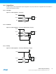
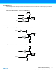
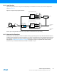
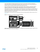
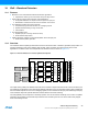

Table Of Contents
- Features
- 1. Ordering Information
- 2. Typical Applications
- 3. Pinout and Block Diagram
- 4. Overview
- 5. Resources
- 6. Capacitive Touch Sensing
- 7. CPU
- 8. Memories
- 9. EDMA – Enhanced DMA Controller
- 10. Event System
- 11. System Clock and Clock options
- 11.1 Features
- 11.2 Overview
- 11.3 Clock Sources
- 11.3.1 32kHz Ultra Low Power Internal Oscillator
- 11.3.2 32.768kHz Calibrated Internal Oscillator
- 11.3.3 32.768kHz Crystal Oscillator
- 11.3.4 0.4 - 16MHz Crystal Oscillator
- 11.3.5 8MHz Calibrated Internal Oscillator
- 11.3.6 32MHz Run-time Calibrated Internal Oscillator
- 11.3.7 External Clock Sources
- 11.3.8 PLL with 1x-31x Multiplication Factor
- 12. Power Management and Sleep Modes
- 13. System Control and Reset
- 14. WDT – Watchdog Timer
- 15. Interrupts and Programmable Multilevel Interrupt Controller
- 16. I/O Ports
- 17. Timer Counter Type 4 and 5
- 18. WeX – Waveform Extension
- 19. Hi-Res – High Resolution Extension
- 20. Fault Extension
- 21. RTC – 16-bit Real-Time Counter
- 22. TWI – Two-Wire Interface
- 23. SPI – Serial Peripheral Interface
- 24. USART
- 25. IRCOM – IR Communication Module
- 26. XCL – XMEGA Custom Logic Module
- 27. CRC – Cyclic Redundancy Check Generator
- 28. ADC – 12-bit Analog to Digital Converter
- 29. DAC – Digital to Analog Converter
- 30. AC – Analog Comparator
- 31. Programming and Debugging
- 32. Pinout and Pin Functions
- 33. Peripheral Module Address Map
- 34. Instruction Set Summary
- 35. Packaging Information
- 36. Electrical Characteristics
- 36.1 Absolute Maximum Ratings
- 36.2 General Operating Ratings
- 36.3 Current Consumption
- 36.4 Wake-up Time from Sleep Modes
- 36.5 I/O Pin Characteristics
- 36.6 ADC Characteristics
- 36.7 DAC Characteristics
- 36.8 Analog Comparator Characteristics
- 36.9 Bandgap and Internal 1.0V Reference Characteristics
- 36.10 External Reset Characteristics
- 36.11 Power-on Reset Characteristics
- 36.12 Flash and EEPROM Characteristics
- 36.13 Clock and Oscillator Characteristics
- 36.13.1 Calibrated 32.768kHz Internal Oscillator Characteristics
- 36.13.2 Calibrated 8MHz Internal Oscillator Characteristics
- 36.13.3 Calibrated and Tunable 32MHz Internal Oscillator Characteristics
- 36.13.4 32 kHz Internal ULP Oscillator Characteristics
- 36.13.5 Internal Phase Locked Loop (PLL) Characteristics
- 36.13.6 External Clock Characteristics
- 36.13.7 External 16MHz Crystal Oscillator and XOSC Characteristics
- 36.13.8 External 32.768kHz Crystal Oscillator and TOSC Characteristics
- 36.14 SPI Characteristics
- 36.15 Two-Wire Interface Characteristics
- 37. Typical Characteristics
- 37.1 Current Consumption
- 37.2 I/O Pin Characteristics
- 37.3 ADC Characteristics
- 37.4 DAC Characteristics
- 37.5 AC Characteristics
- 37.6 Internal 1.0V Reference Characteristics
- 37.7 BOD Characteristics
- 37.8 External Reset Characteristics
- 37.9 Power-on Reset Characteristics
- 37.10 Oscillator Characteristics
- 37.11 Two-wire Interface Characteristics
- 37.12 PDI Characteristics
- 38. Errata – ATxmega32E5 / ATxmega16E5 / ATxmega8E5
- 39. Revision History
- Table of Contents

34
XMEGA E5 [DATASHEET]
Atmel-8153J–AVR-ATxmega8E5-ATxmega16E5-ATxmega32E5_Datasheet–11/2014
17. Timer Counter Type 4 and 5
17.1 Features
Three 16-bit timer/counter
One timer/counter of type 4
Two timer/counter of type 5
32-bit timer/counter support by cascading two timer/counters
Up to four compare or capture (CC) channels
Four CC channels for timer/counters of type 4
Two CC channels for timer/counters of type 5
Double buffered timer period setting
Double buffered CC channels
Waveform generation modes:
Frequency generation
Single-slope pulse width modulation
Dual-slope pulse width modulation
Input capture:
Input capture with noise cancelling
Frequency capture
Pulse width capture
32-bit input capture
Timer overflow and error interrupts/events
One compare match or input capture interrupt/event per CC channel
Can be used with event system for:
Quadrature decoding
Count and direction control
Input capture
Can be used with EDMA and to trigger EDMA transactions
High-resolution extension
Increases frequency and waveform resolution by 4x (2-bit) or 8x (3-bit)
Waveform extension
Low- and high-side output with programmable dead-time insertion (DTI)
Fault extention
Event controlled fault protection for safe disabling of drivers
17.2 Overview
Atmel AVR XMEGA devices have a set of flexible, 16-bit timer/counters (TC). Their capabilities include accurate program
execution timing, frequency and waveform generation, and input capture with time and frequency measurement of digital
signals. Two timer/counters can be cascaded to create a 32-bit timer/counter with optional 32-bit input capture.
A timer/counter consists of a base counter and a set of compare or capture (CC) channels. The base counter can be
used to count clock cycles or events. It has direction control and period setting that can be used for timing. The CC
channels can be used together with the base counter to do compare match control, frequency generation, and pulse
width modulation (PWM) generation, as well as various input capture operations. A timer/counter can be configured for
either capture, compare, or capture and compare function.
A timer/counter can be clocked and timed from the peripheral clock with optional prescaling, or from the event system.
The event system can also be used for direction control, input capture trigger, or to synchronize operations.