
Datasheet
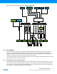
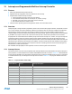
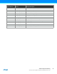
Table Of Contents
- Features
- 1. Ordering Information
- 2. Typical Applications
- 3. Pinout and Block Diagram
- 4. Overview
- 5. Resources
- 6. Capacitive Touch Sensing
- 7. CPU
- 8. Memories
- 9. EDMA – Enhanced DMA Controller
- 10. Event System
- 11. System Clock and Clock options
- 11.1 Features
- 11.2 Overview
- 11.3 Clock Sources
- 11.3.1 32kHz Ultra Low Power Internal Oscillator
- 11.3.2 32.768kHz Calibrated Internal Oscillator
- 11.3.3 32.768kHz Crystal Oscillator
- 11.3.4 0.4 - 16MHz Crystal Oscillator
- 11.3.5 8MHz Calibrated Internal Oscillator
- 11.3.6 32MHz Run-time Calibrated Internal Oscillator
- 11.3.7 External Clock Sources
- 11.3.8 PLL with 1x-31x Multiplication Factor
- 12. Power Management and Sleep Modes
- 13. System Control and Reset
- 14. WDT – Watchdog Timer
- 15. Interrupts and Programmable Multilevel Interrupt Controller
- 16. I/O Ports
- 17. Timer Counter Type 4 and 5
- 18. WeX – Waveform Extension
- 19. Hi-Res – High Resolution Extension
- 20. Fault Extension
- 21. RTC – 16-bit Real-Time Counter
- 22. TWI – Two-Wire Interface
- 23. SPI – Serial Peripheral Interface
- 24. USART
- 25. IRCOM – IR Communication Module
- 26. XCL – XMEGA Custom Logic Module
- 27. CRC – Cyclic Redundancy Check Generator
- 28. ADC – 12-bit Analog to Digital Converter
- 29. DAC – Digital to Analog Converter
- 30. AC – Analog Comparator
- 31. Programming and Debugging
- 32. Pinout and Pin Functions
- 33. Peripheral Module Address Map
- 34. Instruction Set Summary
- 35. Packaging Information
- 36. Electrical Characteristics
- 36.1 Absolute Maximum Ratings
- 36.2 General Operating Ratings
- 36.3 Current Consumption
- 36.4 Wake-up Time from Sleep Modes
- 36.5 I/O Pin Characteristics
- 36.6 ADC Characteristics
- 36.7 DAC Characteristics
- 36.8 Analog Comparator Characteristics
- 36.9 Bandgap and Internal 1.0V Reference Characteristics
- 36.10 External Reset Characteristics
- 36.11 Power-on Reset Characteristics
- 36.12 Flash and EEPROM Characteristics
- 36.13 Clock and Oscillator Characteristics
- 36.13.1 Calibrated 32.768kHz Internal Oscillator Characteristics
- 36.13.2 Calibrated 8MHz Internal Oscillator Characteristics
- 36.13.3 Calibrated and Tunable 32MHz Internal Oscillator Characteristics
- 36.13.4 32 kHz Internal ULP Oscillator Characteristics
- 36.13.5 Internal Phase Locked Loop (PLL) Characteristics
- 36.13.6 External Clock Characteristics
- 36.13.7 External 16MHz Crystal Oscillator and XOSC Characteristics
- 36.13.8 External 32.768kHz Crystal Oscillator and TOSC Characteristics
- 36.14 SPI Characteristics
- 36.15 Two-Wire Interface Characteristics
- 37. Typical Characteristics
- 37.1 Current Consumption
- 37.2 I/O Pin Characteristics
- 37.3 ADC Characteristics
- 37.4 DAC Characteristics
- 37.5 AC Characteristics
- 37.6 Internal 1.0V Reference Characteristics
- 37.7 BOD Characteristics
- 37.8 External Reset Characteristics
- 37.9 Power-on Reset Characteristics
- 37.10 Oscillator Characteristics
- 37.11 Two-wire Interface Characteristics
- 37.12 PDI Characteristics
- 38. Errata – ATxmega32E5 / ATxmega16E5 / ATxmega8E5
- 39. Revision History
- Table of Contents
28
XMEGA E5 [DATASHEET]
Atmel-8153J–AVR-ATxmega8E5-ATxmega16E5-ATxmega32E5_Datasheet–11/2014
15. Interrupts and Programmable Multilevel Interrupt Controller
15.1 Features
Short and predictable interrupt response time
Separate interrupt configuration and vector address for each interrupt
Programmable multilevel interrupt controller
Interrupt prioritizing according to level and vector address
Three selectable interrupt levels for all interrupts: low, medium, and high
Selectable, round-robin priority scheme within low-level interrupts
Non-maskable interrupts for critical functions
Interrupt vectors optionally placed in the application section or the boot loader section
15.2 Overview
Interrupts signal a change of state in peripherals, and this can be used to alter program execution. Peripherals can have
one or more interrupts, and all are individually enabled and configured. When an interrupt is enabled and configured, it
will generate an interrupt request when the interrupt condition is present. The programmable multilevel interrupt
controller (PMIC) controls the handling and prioritizing of interrupt requests. When an interrupt request is acknowledged
by the PMIC, the program counter is set to point to the interrupt vector, and the interrupt handler can be executed.
All peripherals can select between three different priority levels for their interrupts: low, medium, and high. Interrupts are
prioritized according to their level and their interrupt vector address. Medium-level interrupts will interrupt low-level
interrupt handlers. High-level interrupts will interrupt both medium- and low-level interrupt handlers. Within each level, the
interrupt priority is decided from the interrupt vector address, where the lowest interrupt vector address has the highest
interrupt priority. Low-level interrupts have an optional round-robin scheduling scheme to ensure that all interrupts are
serviced within a certain amount of time.
Non-maskable interrupts (NMI) are also supported, and can be used for system critical functions.
15.3 Interrupt Vectors
The interrupt vector is the sum of the peripheral’s base interrupt address and the offset address for specific interrupts in
each peripheral. The base addresses for the Atmel AVR XMEGA E5 devices are shown in Table 15-1. Offset addresses
for each interrupt available in the peripheral are described for each peripheral in the XMEGA AU manual. For peripherals
or modules that have only one interrupt, the interrupt vector is shown in Table 15-1. The program address is the word
address.
Table 15-1. Peripheral Module Address Map
Program address
(base address)
Source Interrupt description
0x0000 RESET
0x0002 OSCF_INT_vect Crystal oscillator failure and PLL lock failure interrupt vector (NMI)
0x0004 PORTR_INT_vect Port R Interrupt vector
0x0006 EDMA_INT_base EDMA Controller Interrupt base
0x000E RTC_INT_base Real time counter interrupt base
0x0012 PORTC_INT_vect Port C interrupt vector
0x0014 TWIC_INT_base Two-wire interface on Port C interrupt base
0x0018 TCC4_INT_base Timer/counter 4 on port C interrupt base