
Datasheet
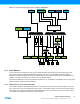


Table Of Contents
- Features
- 1. Ordering Information
- 2. Typical Applications
- 3. Pinout and Block Diagram
- 4. Overview
- 5. Resources
- 6. Capacitive Touch Sensing
- 7. CPU
- 8. Memories
- 9. EDMA – Enhanced DMA Controller
- 10. Event System
- 11. System Clock and Clock options
- 11.1 Features
- 11.2 Overview
- 11.3 Clock Sources
- 11.3.1 32kHz Ultra Low Power Internal Oscillator
- 11.3.2 32.768kHz Calibrated Internal Oscillator
- 11.3.3 32.768kHz Crystal Oscillator
- 11.3.4 0.4 - 16MHz Crystal Oscillator
- 11.3.5 8MHz Calibrated Internal Oscillator
- 11.3.6 32MHz Run-time Calibrated Internal Oscillator
- 11.3.7 External Clock Sources
- 11.3.8 PLL with 1x-31x Multiplication Factor
- 12. Power Management and Sleep Modes
- 13. System Control and Reset
- 14. WDT – Watchdog Timer
- 15. Interrupts and Programmable Multilevel Interrupt Controller
- 16. I/O Ports
- 17. Timer Counter Type 4 and 5
- 18. WeX – Waveform Extension
- 19. Hi-Res – High Resolution Extension
- 20. Fault Extension
- 21. RTC – 16-bit Real-Time Counter
- 22. TWI – Two-Wire Interface
- 23. SPI – Serial Peripheral Interface
- 24. USART
- 25. IRCOM – IR Communication Module
- 26. XCL – XMEGA Custom Logic Module
- 27. CRC – Cyclic Redundancy Check Generator
- 28. ADC – 12-bit Analog to Digital Converter
- 29. DAC – Digital to Analog Converter
- 30. AC – Analog Comparator
- 31. Programming and Debugging
- 32. Pinout and Pin Functions
- 33. Peripheral Module Address Map
- 34. Instruction Set Summary
- 35. Packaging Information
- 36. Electrical Characteristics
- 36.1 Absolute Maximum Ratings
- 36.2 General Operating Ratings
- 36.3 Current Consumption
- 36.4 Wake-up Time from Sleep Modes
- 36.5 I/O Pin Characteristics
- 36.6 ADC Characteristics
- 36.7 DAC Characteristics
- 36.8 Analog Comparator Characteristics
- 36.9 Bandgap and Internal 1.0V Reference Characteristics
- 36.10 External Reset Characteristics
- 36.11 Power-on Reset Characteristics
- 36.12 Flash and EEPROM Characteristics
- 36.13 Clock and Oscillator Characteristics
- 36.13.1 Calibrated 32.768kHz Internal Oscillator Characteristics
- 36.13.2 Calibrated 8MHz Internal Oscillator Characteristics
- 36.13.3 Calibrated and Tunable 32MHz Internal Oscillator Characteristics
- 36.13.4 32 kHz Internal ULP Oscillator Characteristics
- 36.13.5 Internal Phase Locked Loop (PLL) Characteristics
- 36.13.6 External Clock Characteristics
- 36.13.7 External 16MHz Crystal Oscillator and XOSC Characteristics
- 36.13.8 External 32.768kHz Crystal Oscillator and TOSC Characteristics
- 36.14 SPI Characteristics
- 36.15 Two-Wire Interface Characteristics
- 37. Typical Characteristics
- 37.1 Current Consumption
- 37.2 I/O Pin Characteristics
- 37.3 ADC Characteristics
- 37.4 DAC Characteristics
- 37.5 AC Characteristics
- 37.6 Internal 1.0V Reference Characteristics
- 37.7 BOD Characteristics
- 37.8 External Reset Characteristics
- 37.9 Power-on Reset Characteristics
- 37.10 Oscillator Characteristics
- 37.11 Two-wire Interface Characteristics
- 37.12 PDI Characteristics
- 38. Errata – ATxmega32E5 / ATxmega16E5 / ATxmega8E5
- 39. Revision History
- Table of Contents

23
XMEGA E5 [DATASHEET]
Atmel-8153J–AVR-ATxmega8E5-ATxmega16E5-ATxmega32E5_Datasheet–11/2014
12. Power Management and Sleep Modes
12.1 Features
Power management for adjusting power consumption and functions
Five sleep modes
Idle
Power down
Power save
Standby
Extended standby
Power reduction register to disable clock and turn off unused peripherals in active and idle modes
12.2 Overview
Various sleep modes and clock gating are provided in order to tailor power consumption to application requirements.
This enables the Atmel AVR XMEGA microcontroller to stop unused modules to save power.
All sleep modes are available and can be entered from active mode. In active mode, the CPU is executing application
code. When the device enters sleep mode, program execution is stopped and interrupts or a reset is used to wake the
device again. The application code decides which sleep mode to enter and when. Interrupts from enabled peripherals
and all enabled reset sources can restore the microcontroller from sleep to active mode.
In addition, power reduction registers provide a method to stop the clock to individual peripherals from software. When
this is done, the current state of the peripheral is frozen, and there is no power consumption from that peripheral. This
reduces the power consumption in active mode and idle sleep modes and enables much more fine-tuned power
management than sleep modes alone.
12.3 Sleep Modes
Sleep modes are used to shut down modules and clock domains in the microcontroller in order to save power. XMEGA
microcontrollers have five different sleep modes tuned to match the typical functional stages during application
execution. A dedicated sleep instruction (SLEEP) is available to enter sleep mode. Interrupts are used to wake the
device from sleep, and the available interrupt wake-up sources are dependent on the configured sleep mode. When an
enabled interrupt occurs, the device will wake up and execute the interrupt service routine before continuing normal
program execution from the first instruction after the SLEEP instruction. If other, higher priority interrupts are pending
when the wake-up occurs, their interrupt service routines will be executed according to their priority before the interrupt
service routine for the wake-up interrupt is executed. After wake-up, the CPU is halted for four cycles before execution
starts.
The content of the register file, SRAM and registers are kept during sleep. If a reset occurs during sleep, the device will
reset, start up, and execute from the reset vector.
12.3.1 Idle Mode
In idle mode the CPU and nonvolatile memory are stopped (note that any ongoing programming will be completed), but
all peripherals, including the interrupt controller, event system and EDMA controller are kept running. Any enabled
interrupt will wake the device.
12.3.2 Power-down Mode
In power-down mode, all clocks, including the real-time counter clock source, are stopped. This allows operation only of
asynchronous modules that do not require a running clock. The only interrupts that can wake up the MCU are the two-
wire interface address match interrupt and asynchronous port interrupts.