
Datasheet

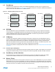

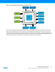
Table Of Contents
- Features
- 1. Ordering Information
- 2. Typical Applications
- 3. Pinout and Block Diagram
- 4. Overview
- 5. Resources
- 6. Capacitive Touch Sensing
- 7. CPU
- 8. Memories
- 9. EDMA – Enhanced DMA Controller
- 10. Event System
- 11. System Clock and Clock options
- 11.1 Features
- 11.2 Overview
- 11.3 Clock Sources
- 11.3.1 32kHz Ultra Low Power Internal Oscillator
- 11.3.2 32.768kHz Calibrated Internal Oscillator
- 11.3.3 32.768kHz Crystal Oscillator
- 11.3.4 0.4 - 16MHz Crystal Oscillator
- 11.3.5 8MHz Calibrated Internal Oscillator
- 11.3.6 32MHz Run-time Calibrated Internal Oscillator
- 11.3.7 External Clock Sources
- 11.3.8 PLL with 1x-31x Multiplication Factor
- 12. Power Management and Sleep Modes
- 13. System Control and Reset
- 14. WDT – Watchdog Timer
- 15. Interrupts and Programmable Multilevel Interrupt Controller
- 16. I/O Ports
- 17. Timer Counter Type 4 and 5
- 18. WeX – Waveform Extension
- 19. Hi-Res – High Resolution Extension
- 20. Fault Extension
- 21. RTC – 16-bit Real-Time Counter
- 22. TWI – Two-Wire Interface
- 23. SPI – Serial Peripheral Interface
- 24. USART
- 25. IRCOM – IR Communication Module
- 26. XCL – XMEGA Custom Logic Module
- 27. CRC – Cyclic Redundancy Check Generator
- 28. ADC – 12-bit Analog to Digital Converter
- 29. DAC – Digital to Analog Converter
- 30. AC – Analog Comparator
- 31. Programming and Debugging
- 32. Pinout and Pin Functions
- 33. Peripheral Module Address Map
- 34. Instruction Set Summary
- 35. Packaging Information
- 36. Electrical Characteristics
- 36.1 Absolute Maximum Ratings
- 36.2 General Operating Ratings
- 36.3 Current Consumption
- 36.4 Wake-up Time from Sleep Modes
- 36.5 I/O Pin Characteristics
- 36.6 ADC Characteristics
- 36.7 DAC Characteristics
- 36.8 Analog Comparator Characteristics
- 36.9 Bandgap and Internal 1.0V Reference Characteristics
- 36.10 External Reset Characteristics
- 36.11 Power-on Reset Characteristics
- 36.12 Flash and EEPROM Characteristics
- 36.13 Clock and Oscillator Characteristics
- 36.13.1 Calibrated 32.768kHz Internal Oscillator Characteristics
- 36.13.2 Calibrated 8MHz Internal Oscillator Characteristics
- 36.13.3 Calibrated and Tunable 32MHz Internal Oscillator Characteristics
- 36.13.4 32 kHz Internal ULP Oscillator Characteristics
- 36.13.5 Internal Phase Locked Loop (PLL) Characteristics
- 36.13.6 External Clock Characteristics
- 36.13.7 External 16MHz Crystal Oscillator and XOSC Characteristics
- 36.13.8 External 32.768kHz Crystal Oscillator and TOSC Characteristics
- 36.14 SPI Characteristics
- 36.15 Two-Wire Interface Characteristics
- 37. Typical Characteristics
- 37.1 Current Consumption
- 37.2 I/O Pin Characteristics
- 37.3 ADC Characteristics
- 37.4 DAC Characteristics
- 37.5 AC Characteristics
- 37.6 Internal 1.0V Reference Characteristics
- 37.7 BOD Characteristics
- 37.8 External Reset Characteristics
- 37.9 Power-on Reset Characteristics
- 37.10 Oscillator Characteristics
- 37.11 Two-wire Interface Characteristics
- 37.12 PDI Characteristics
- 38. Errata – ATxmega32E5 / ATxmega16E5 / ATxmega8E5
- 39. Revision History
- Table of Contents

16
XMEGA E5 [DATASHEET]
Atmel-8153J–AVR-ATxmega8E5-ATxmega16E5-ATxmega32E5_Datasheet–11/2014
9. EDMA – Enhanced DMA Controller
9.1 Features
The EDMA Controller allows data transfers with minimal CPU intervention
from data memory to data memory
from data memory to peripheral
from peripheral to data memory
from peripheral to peripheral
Four peripheral EDMA channels with separate:
transfer triggers
interrupt vectors
addressing modes
data matching
Two peripheral channels can be combined to one standard channel with separate:
transfer triggers
interrupt vectors
addressing modes
data search
Programmable channel priority
From 1byte to 128KB of data in a single transaction
Up to 64K block transfer with repeat
1 or 2 bytes burst transfers
Multiple addressing modes
Static
Increment
Optional reload of source and destination address at the end of each
Burst
Block
Transaction
Optional Interrupt on end of transaction
Optional connection to CRC Generator module for CRC on EDMA data
9.2 Overview
The four-channel enhanced direct memory access (EDMA) controller can transfer data between memories and
peripherals, and thus offload these tasks from the CPU. It enables high data transfer rates with minimum CPU
intervention, and frees up CPU time. The four EDMA channels enable up to four independent and parallel transfers.
The EDMA controller can move data between SRAM and peripherals, between SRAM locations and directly between
peripheral registers. With access to all peripherals, the EDMA controller can handle automatic transfer of data to/from
communication modules. The EDMA controller can also read from EEPROM memory.
Data transfers are done in continuous bursts of 1 or 2 bytes. They build block transfers of configurable size from 1 byte to
64KB. Repeat option can be used to repeat once each block transfer for single transactions up to 128KB. Source and
destination addressing can be static or incremental. Automatic reload of source and/or destination addresses can be
done after each burst or block transfer, or when a transaction is complete. Application software, peripherals, and events
can trigger EDMA transfers.
The four EDMA channels have individual configuration and control settings. This includes source, destination, transfer
triggers, and transaction sizes. They have individual interrupt settings. Interrupt requests can be generated when a
transaction is complete or when the EDMA controller detects an error on an EDMA channel.
To enable flexibility in transfers, channels can be interlinked so that the second takes over the transfer when the first is
finished.