
Datasheet

89
XMEGA B1 [DATASHEET]
Atmel-8330H-AVR-ATxmega64B1-128B1_datasheet–12/2014
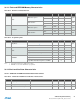
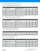
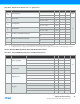
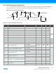
36.16 Two-wire Interface Characteristics
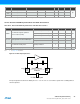
Table 36-30 describes the requirements for devices connected to the Two-wire Serial Bus. The Atmel AVR XMEGA Two-
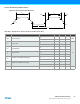
wire Interface meets or exceeds these requirements under the noted conditions. Timing symbols refer to Figure 36-7.
Figure 36-7. Two-wire Interface Bus Timing
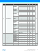
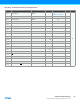
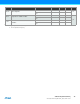
Table 36-30. Two-wire Serial Bus Characteristics
t
HD;STA
t
of
SDA
SCL
t
LOW
t
HIGH
t
SU;STA
t
BUF
t
r
t
HD;DAT
t
SU;DAT
t
SU;STO
Symbol Parameter Condition Min. Typ. Max. Units
V
IH
Input high voltage 0.7*V
CC
V
CC
+0.5
V
V
IL
Input low voltage -0.5 0.3*V
CC
V
hys
Hysteresis of Schmitt trigger inputs 0.05V
CC
(1)
0
V
OL
Output low voltage 3mA, sink current 0 0.4
t
r
Rise time for both SDA and SCL 20+0.1C
b
(1)(2)
300
nst
of
Output fall time from V
IHmin
to V
ILmax
10pF < C
b
< 400pF
(2)
20+0.1C
b
(1)(2)
250
t
SP
Spikes suppressed by input filter 0 50
I
I
Input current for each I/O pin 0.1V
CC
< V
I
< 0.9V
CC
-10 10 µA
C
I
Capacitance for each I/O pin 10 pF
f
SCL
SCL clock frequency f
PER
(3)
>max(10f
SCL
, 250kHz) 0 400 kHz
R
P
Value of pull-up resistor
f
SCL
100kHz
f
SCL
> 100kHz
t
HD;STA
Hold time (repeated) START condition
f
SCL
100kHz 4.0
µs
f
SCL
> 100kHz 0.6
t
LOW
Low period of SCL clock
f
SCL
100kHz 4.7
f
SCL
> 100kHz 1.3
t
HIGH
High period of SCL clock
f
SCL
100kHz 4.0
f
SCL
> 100kHz 0.6
t
SU;STA
Set-up time for a repeated START condition
f
SCL
100kHz 4.7
f
SCL
> 100kHz 0.6
t
HD;DAT
Data hold time
f
SCL
100kHz 0 3.5
f
SCL
> 100kHz 0 0.9
V
CC
0.4V–
3mA
--------------------------- -
100ns
C
b
-------------- -
300ns
C
b
-------------- -