
Datasheet

83
XMEGA B1 [DATASHEET]
Atmel-8330H-AVR-ATxmega64B1-128B1_datasheet–12/2014
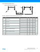
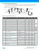
36.14.6 External Clock Characteristics
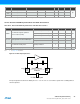
Figure 36-3. External Clock Drive Waveform
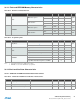
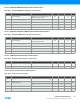
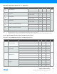
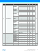
Table 36-25. External Clock used as System Clock without Prescaling
Note: 1. The maximum frequency vs. supply voltage is linear between 1.8V and 2.7V, and the same applies for all other parameters with supply voltage conditions.
t
CH
t
CL
t
CK
t
CH
V
IL1
V
IH1
t
CR
t
CF
Symbol Parameter Condition Min. Typ. Max. Units
1/t
CK
Clock frequency
(1)
V
CC
= 1.6 - 1.8V 0 12
MHz
V
CC
= 2.7 - 3.6V 0 32
t
CK
Clock period
V
CC
= 1.6 - 1.8V 83.3
ns
V
CC
= 2.7 - 3.6V 31.5
t
CH
Clock high time
V
CC
= 1.6 - 1.8V 30.0
V
CC
= 2.7 - 3.6V 12.5
t
CL
Clock low time
V
CC
= 1.6 - 1.8V 30.0
V
CC
= 2.7 - 3.6V 12.5
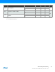
t
CR
Rise time (for maximum frequency)
V
CC
= 1.6 - 1.8V 10
V
CC
= 2.7 - 3.6V 3
t
CF
Fall time (for maximum frequency)
V
CC
= 1.6 - 1.8V 10
V
CC
= 2.7 - 3.6V 3
t
CK
Change in period from one clock cycle to the next 10 %