
Datasheet

74
XMEGA B1 [DATASHEET]
Atmel-8330H-AVR-ATxmega64B1-128B1_datasheet–AVR–12/2014
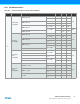
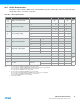
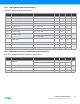
Notes: 1. All parameters measured as the difference in current consumption between module enabled and disabled. All data at V
CC
= 3.0V, Clk
SYS
= 1MHz External clock
without prescaling, T = 25°C unless other conditions are given.
2. LCD configuration: internal voltage generation, 32Hz low power frame rate, 1/3 bias, clocked by low power 32.768kHz TOSC.
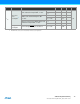
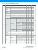
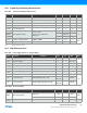
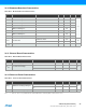
36.4 Wake-up Time from Sleep Modes
Table 36-6. Device Wake-up Time from Sleep Modes with Various System Clock Sources
Note: 1. The wake-up time is the time from the wake-up request is given until the peripheral clock is available on pin, see Figure 36-2 on page 74. All peripherals and
modules start execution from the first clock cycle, expect the CPU that is halted for four clock cycles before program execution starts.
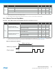
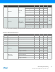
Figure 36-2. Wake-up Time Definition
I
CC
AC 440
µADMA 615Kbps between I/O registers and SRAM 115
USART Rx and Tx enabled, 9600 BAUD 9
Flash memory and EEPROM programming 4.4 mA
Symbol Parameter Condition Min. Typ. Max. Units
t
wakeup
Wake-up time from Idle,
Standby, and Extend Standby
External 2MHz clock 2
µs
32.768kHz internal oscillator 120
2MHz internal oscillator 2
32MHz internal oscillator 0.2
Wake-up time from Power-save
and Power-down mode
External 2MHz clock 4.5
32.768kHz internal oscillator 320
2MHz internal oscillator 9
32MHz internal oscillator 5
Symbol Parameter Condition
(1)
Min. Typ. Max. Units
Wake-up request
Clock output
Wake-up time