
Datasheet

56
XMEGA B1 [DATASHEET]
Atmel-8330H-AVR-ATxmega64B1-128B1_datasheet–AVR–12/2014
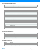
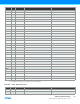
32.2 Alternate Pin Functions
The tables below show the primary/default function for each pin on a port in the first column, the pin number in the
second column, and then all alternate pin functions in the remaining columns. The head row shows what peripheral that
enable and use the alternate pin functions.
For better flexibility, some alternate functions also have selectable pin locations for their functions, this is noted under the
first table where this apply.
Table 32-1. Port A - Alternate Functions
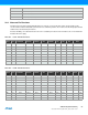
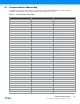
Table 32-2. Port B - Alternate Functions
TCK JTAG Test Clock
TDI JTAG Test Data In
TDO JTAG Test Data Out
TMS JTAG Test Mode Select
PORT A PIN # INTERRUPT
ADCA POS/
GAINPOS
ADCB POS/
GAINPOS
ADCA
NEG
ADCA
GAINNEG
ACA
POS
ACA
NEG
ACA
OUT REFA
PA0 82 SYNC ADC0 ADC8 ADC0 AC0 AC0 AREF
PA1 83 SYNC ADC1 ADC9 ADC1 AC1 AC1
PA2 84 SYNC/ASYNC ADC2 ADC10 ADC2 AC2
PA3 85 SYNC ADC3 ADC11 ADC3 AC3 AC3
PA4 86 SYNC ADC4 ADC12 ADC4 AC4
PA5 87 SYNC ADC5 ADC13 ADC5 AC5 AC5
PA6 88 SYNC ADC6 ADC14 ADC6 AC6 AC1OUT
PA7 89 SYNC ADC7 ADC15 ADC7 AC7 AC0OUT
PORT B PIN # INTERRUPT
ADCA POS/
GAINPOS
ADCB POS/
GAINPOS
ADCB
NEG
ADCB
GAINNEG
ACB
POS
ACB
NEG
ACB
OUT
REFB JTAG
AGND 90
AVCC 91
PB0 92 SYNC ADC8 ADC0 ADC0 AC0 AC0 AREF
PB1 93 SYNC ADC9 ADC1 ADC1 AC1 AC1
PB2 94 SYNC/ASYNC ADC10 ADC2 ADC2 AC2
PB3 95 SYNC ADC11 ADC3 ADC3 AC3 AC3
PB4 96 SYNC ADC12 ADC4 ADC4 AC4 TMS
PB5 97 SYNC ADC13 ADC5 ADC5 AC5 AC5 TDI
PB6 98 SYNC ADC14 ADC6 ADC6 AC6 AC1OUT TCK
PB7 99 SYNC ADC15 ADC7 ADC7 AC7 AC0OUT TDO