
Datasheet

54
XMEGA B1 [DATASHEET]
Atmel-8330H-AVR-ATxmega64B1-128B1_datasheet–AVR–12/2014
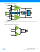
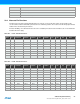
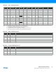
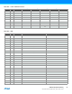
32. Pinout and Pin Functions
The device pinout is shown in “Pinout/Block Diagram” on page 4. In addition to general purpose I/O functionality, each
pin can have several alternate functions. This will depend on which peripheral is enabled and connected to the actual pin.
Only one of the pin functions can be used at time.
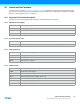
32.1 Alternate Pin Function Description
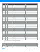
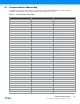
The tables below show the notation for all pin functions available and describe its function.
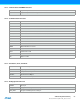
32.1.1 Operation/Power Supply
32.1.2 Port Interrupt Functions
32.1.3 Analog Functions
32.1.4 LCD Functions
V
CC
Digital supply voltage
AV
CC
Analog supply voltage
GND Ground
AGND Analog Ground
SYNC Port pin with full synchronous and limited asynchronous interrupt function
ASYNC Port pin with full synchronous and full asynchronous interrupt function
ACn Analog Comparator input pin n
ACnOUT Analog Comparator n Output
ADCn Analog to Digital Converter input pin n
AREF Analog Reference input pin
SEGn LCD Segment Drive Output n
COMn LCD Common Drive Output n
VLCD LCD Voltage Multiplier Output
BIAS2 LCD Intermediate Voltage 2 Output (VLCD * 2/3)
BIAS1 LCD Intermediate Voltage 1 Output (VLCD * 1/3)
CAPH LCD High End Of Flying Capacitor
CAPL LCD Low End Of Flying Capacitor