
Datasheet

36
XMEGA B1 [DATASHEET]
Atmel-8330H-AVR-ATxmega64B1-128B1_datasheet–AVR–12/2014
17. TC2 –16-bit Timer/Counter Type 2
17.1 Features
A system of two 8-bit timer/counters
Low-byte timer/counter
High-byte timer/counter
Eight compare channels
Four compare channels for the low-byte timer/counter
Four compare channels for the high-byte timer/counter
Waveform generation
Single slope pulse width modulation
Timer underflow interrupts/events
One compare match interrupt/event per compare channel for the low-byte timer/counter
Can be used with the event system for count control
Can be used to trigger DMA transactions
High-resolution extension increases frequency and waveform resolution by 4x or 8x
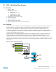
17.2 Overview
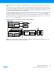
A timer/counter 2 is realized when a timer/counter 0 is set in split mode. It is a system of two 8-bit timer/counters, each
with four compare channels. This results in eight configurable pulse width modulation (PWM) channels with individually
controlled duty cycles, and is intended for applications that require a high number of PWM channels.
The two 8-bit timer/counters in this system are referred to as the low-byte timer/counter and high-byte timer/counter,
respectively. The difference between them is that only the low-byte timer/counter can be used to generate compare
match interrupts, events and DMA triggers.
The two 8-bit timer/counters have a shared clock source and separate period and compare settings. They can be clocked
and timed from the peripheral clock, with optional prescaling, or from the event system. The counters are always
counting down.
The timer/counter 2 is set back to timer/counter 0 by setting it in normal mode; hence, one timer/counter can exist only as
either type 0 or type 2.
PORTC and PORTE each has one Timer/Counter 2. Notation of these are TCC2 (Time/Counter C2) and TCE2
respectively.