
Datasheet

16
XMEGA B1 [DATASHEET]
Atmel-8330H-AVR-ATxmega64B1-128B1_datasheet–AVR–12/2014
7.11 JTAG Disable
It is possible to disable the JTAG interface from the application software. This will prevent all external JTAG access to the
device until the next device reset or until JTAG is enabled again from the application software. As long as JTAG is
disabled, the I/O pins required for JTAG can be used as normal I/O pins.
7.12 I/O Memory Protection
Some features in the device are regarded as critical for safety in some applications. Due to this, it is possible to lock the
I/O register related to the clock system, the event system, and the advanced waveform extensions. As long as the lock is
enabled, all related I/O registers are locked and they can not be written from the application software. The lock registers
themselves are protected by the configuration change protection mechanism.
7.13 Flash and EEPROM Page Size
The flash program memory and EEPROM data memory are organized in pages. The pages are word accessible for the
flash and byte accessible for the EEPROM.
Table 7-2 on page 16 shows the Flash Program Memory organization. Flash write and erase operations are performed
on one page at a time, while reading the Flash is done one byte at a time. For Flash access the Z-pointer (Z[m:n]) is used
for addressing. The most significant bits in the address (FPAGE) give the page number and the least significant address
bits (FWORD) give the word in the page.
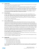
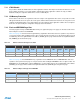
Table 7-2. Number of Words and Pages in the Flash
Table 7-3 on page 16 shows EEPROM memory organization for the XMEGA B1 devices. EEEPROM write and erase
operations can be performed one page or one byte at a time, while reading the EEPROM is done one byte at a time. For
EEPROM access the NVM address register (ADDR[m:n]) is used for addressing. The most significant bits in the address
(E2PAGE) give the page number and the least significant address bits (E2BYTE) give the byte in the page.
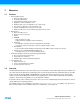
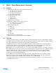
Table 7-3. Number of Bytes and Pages in the EEPROM
Devices PC size Flash Page size FWORD FPAGE Application Boot
bits bytes words Size
No. of
pages
Size
No. of
pages
ATxmega64B1 16 64K + 4K 128 Z[7:1] Z[16:8] 64K 256 4K 16
ATxmega128B1 17 128K + 8K 128 Z[8:1] Z[17:9] 128K 512 8K 32
Devices EEPROM Page size E2BYTE E2PAGE No. of pages
Size Bytes
ATxmega64B1 2K 32 ADDR[4:0] ADDR[10:5] 64
ATxmega128B1 2K 32 ADDR[4:0] ADDR[10:5] 64