
Specifications


85
AT90S8515
0841G–09/01
Parallel Programming
Characteristics
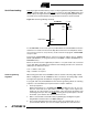
Figure 63. Parallel Programming Timing
Notes: 1. Use t
WLWH_CE
for Chip Erase and t
WLWH_PFB
for programming the Fuse bits.
2. If t
WLWH
is held longer than t
WLRH
, no RDY/BSY pulse will be seen.
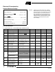
Table 30. Parallel Programming Characteristics, T
A
= 25°C ± 10%, V
CC
= 5V ± 10%
Symbol Parameter Min Typ Max Units
V
PP
Programming Enable Voltage 11.5 12.5 V
I
PP
Programming Enable Current 250.0 µA
t
DVXH
Data and Control Setup before XTAL1 High 67.0 ns
t
XHXL
XTAL1 Pulse Width High 67.0 ns
t
XLDX
Data and Control Hold after XTAL1 Low 67.0 ns
t
XLWL
XTAL1 Low to WR Low 67.0 ns
t
BVWL
BS Valid to WR Low 67.0 ns
t
RHBX
BS Hold after RDY/BSY High 67.0 ns
t
WLWH
WR Pulse Width Low
(1)
67.0 ns
t
WHRL
WR High to RDY/BSY Low
(2)
20.0 ns
t
WLRH
WR Low to RDY/BSY High
(2)
0.5 0.7 0.9 ms
t
XLOL
XTAL1 Low to OE Low 67.0 ns
t
OLDV
OE Low to DATA Valid 20.0 ns
t
OHDZ
OE High to DATA Tri-stated 20.0 ns
t
WLWH_CE
WR Pulse Width Low for Chip Erase 5.0 10.0 15.0 ms
t
WLWH_PFB
WR Pulse Width Low for Programming the Fuse
Bits 1.0 1.5 1.8 ms
Data & Control
(DATA, XA0/1, BS)
DATA
Write
Read
XTAL1
t
XHXL
t
WLWH
t
DVXH
t
XLOL
t
OLDV
t
WHRL
t
WLRH
WR
RDY/BSY
OE
t
XLDX
t
XLWL
t
RHBX
t
OHDZ
t
BVWL