
Specifications


21
AT90S8515
0841G–09/01
into T by the BST instruction and a bit in T can be copied into a bit in a register in the
register file by the BLD instruction.
• Bit 5 – H: Half-carry Flag
The half-carry flag H indicates a half-carry in some arithmetic operations. See the
Instruction Set description for detailed information.
• Bit 4 – S: Sign Bit, S = N
⊄⊕ V
The S-bit is always an exclusive or between the negative flag N and the two’s comple-
ment overflow flag V. See the Instruction Set description for detailed information.
• Bit 3 – V: Two’s Complement Overflow Flag
The two’s complement overflow flag V supports two’s complement arithmetics. See the
Instruction Set description for detailed information.
• Bit 2 – N: Negative Flag
The negative flag N indicates a negative result after the different arithmetic and logic
operations. See the Instruction Set description for detailed information.
• Bit 1 – Z: Zero Flag
The zero flag Z indicates a zero result after the different arithmetic and logic operations.
See the Instruction Set description for detailed information.
• Bit 0 – C: Carry Flag
The carry flag C indicates a carry in an arithmetic or logic operation. See the Instruction
Set description for detailed information.
Note that the Status Register is not automatically stored when entering an interrupt rou-
tine and restored when returning from an interrupt routine. This must be handled by
software.
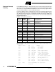
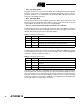
Stack Pointer – SP The general AVR 16-bit Stack Pointer is effectively built up of two 8-bit registers in the
I/O space locations $3E ($5E) and $3D ($5D). As the AT90S8515 supports up to 64 Kb
external SRAM, all 16 bits are used.
The Stack Pointer points to the data SRAM stack area where the Subroutine and Inter-
rupt stacks are located. This stack space in the data SRAM must be defined by the
program before any subroutine calls are executed or interrupts are enabled. The Stack
Pointer must be set to point above $60. The Stack Pointer is decremented by 1 when
data is pushed onto the stack with the PUSH instruction and it is decremented by 2
when an address is pushed onto the stack with subroutine calls and interrupts. The
Stack Pointer is incremented by 1 when data is popped from the stack with the POP
instruction and it is incremented by 2 when an address is popped from the stack with
return from subroutine RET or return from interrupt RETI.
Bit 151413121110 9 8
$3E ($5E) SP15 SP14 SP13 SP12 SP11 SP10 SP9 SP8 SPH
$3D ($5D) SP7 SP6 SP5 SP4 SP3 SP2 SP1 SP0 SPL
76543210
Read/Write R/W R/W R/W R/W R/W R/W R/W R/W
R/W R/W R/W R/W R/W R/W R/W R/W
Initial Value00000000
00000000