
User`s guide


www.uTasker.com
µ
Tasker – AT91SAM7X Tutorial
V1.4
uTaskerV1.4_SAM7X.doc/0.03 16/36 31.07.2009
You should be done within a few minutes….
Are you surprised that it behaves the same as the simulator? You shouldn’t really be
because that is exactly what the simulator is all about. It allows you to test your real code in
real time and once it is working as you want it to, then you can transfer it to the real target. In
fact you will find that your real target is not really necessary for most of your development
work. Develop on the simulator and ship on the target – that is the way to do things really
efficiently.
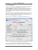
Note that the I/O page allows the LEDs and port lines on the I/O port connector on the
ATMEL AT91SAM7X-EK to be controlled and the state of these to be displayed. Two LEDs
are set as outputs be default. If PB19 is reconfigured to be an input the blinking LED will no
longer light.
6. Specific Notes concerning the AT91SAM7X
The demo project is designed to work on the SAM7X512, SAM7X256 and the SAM7X128.
For this reason the memory map is set up to use only the SAM7X128 resources. The
memory map thus has the following construction.
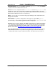
0xffffffff – end of memory space
0xfffa0000 – Start of internal peripherals
0x00207fff – SRAM end { 32k }
0x00200000 – SRAM start
0x0011ffff – FLASH end { 128k }
0x00100000 - FLASH start
0x0001ffff – FLASH end { FLASH ACCESSIBLE ALSO HERE }
0x00000000 - FLASH start { FLASH ACCESSIBLE ALSO HERE }
If larger chips are used this can be modified to make use of the larger internal resources that
are available.