
User`s guide


www.uTasker.com
µ
Tasker – AT91SAM7X Tutorial
V1.4
uTaskerV1.4_SAM7X.doc/0.03 11/36 31.07.2009
Do a quick test: Hover your mouse over the port PB22 in the simulator – it will tell you
which pin it is on your device. Now click – this has toggled the simulated input (each
time you click, it will change state again) – leave it at the low state ‘0’, displayed as ‘v’.
Now refresh the I/O web page by clicking in the Refresh button.
What is the web page now displaying? If it is behaving correctly it will of course be
displaying the new port input state.
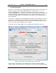
Now we can configure it as an output and control its state from the I/O page:
Set PB22 to be an output, rather than an input and click on “Modify configuration”.
Afterwards set the port state to ‘1’ by setting the first port value from the left and click
on “Modify outputs”. Watch the state of Port PB22 on the simulated device – you will
see that the output is now set and now your lawn would get the water it has been
waiting for!
Set the state to ‘0’ and it will be turned off. In this example web page, all of the 4
Ports PB22..PB19 outputs can be controlled individually.
PB19 is used as a RUN LED in the demo project and so is configured as an output by
default, as is PB20.
If you would like a certain setting to be returned after every reset of the device, simply
save the setting by clicking on “Save settings as default configuration” and you will
see that they are indeed set automatically when the device is started the next time.
The demo project includes also 16 user controllable outputs. These are automatically
configured as outputs in the project code and can be seen as outputs with state ‘0’
when looking at the simulator. If you now click on the user defined outputs on the I/O
page you will see that they immediately toggle their port output and the state is either
displayed as a grey button when ‘0’ or as red buttons when ‘1’. Also the present state
of the 16 outputs can be saved as default states when the target starts the next time.
Note that these outputs can be mapped to any port and port bit in the demo project –
it shows a useful example of flexible independent output control.
Note also that the outputs 1, 2, 3 and 10 are used by the LCD interface and so cannot
be modified when the graphical LCD is defined.
13. The last setting which we will change before taking a look at the project on the target
hardware is to activate HTTP user authentication and disable the FTP server so that
no one else without our password has entry to the web server and no sneaky person
can change the web pages which we have just programmed…
Browse to the administration page, deactivate FTP and activate HTTP server
authentication before selecting the action to “Modify and save server settings”. Finally
click on “Perform desired action” and close your web browser..
Open the web browser again and enter the device’s address http://192.168.0.3 (or
your address) and this time you will need to enter the user name “ADMIN” and
password “uTasker” to get in.
Try to do something with the FTP server (like transfer the file with Copy_all.bat or
delete the file system contents with delete_all.bat) and you will find that it simply
won’t work anymore. This is because the FTP server is no longer running in the
simulated device and you can rest assured than no one out there will be able to
change anything which you have loaded.
You probable noticed a button at the bottom of the administration page which allows
a file to be searched for and uploaded to the target as a new software version. This is
an example of using the HTTP POST method to transfer data to the embedded
device. The µTasker project for the SAM7X supports the upload of complete new