
User guide

Board Description
4-4 AT91SAM7L-STK Rev. B Starter Kit User Guide
6414A–ATARM–12-Sep-08
4.3 Overview
The AT91SAM7L-STK is designed to be a simple starter board for users to evaluate the performance
and functionality of the AT91SAM7L-series microcontroller. Besides the basic system, the board inte-
grates a 400-segments dot matrix LCD, segment LCD control being one of the main attributes of the
AT91SAM7L, along with other low-power features.
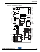
4.4 Processor
The AT91SAM7L-STK is equipped with an AT91SAM7L128 microcontroller in a 128 lead LQFP green
package. The AT91SAM7L128 is a low-power ARM7TDMI Thumb-based microcontroller, targeting bat-
tery powered systems. Various aspects contribute to this, such as: wide supply range (1.8V to 3.6V) for
direct battery power, minimum leakage Power-on Reset, brownout detector, multi-mode power supply
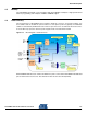
controller, adjustable PLL and more. It also provides a fully integrated 400-segments LCD controller,
including drivers and charge pump for contrast control. The chip runs up to 37 MHz at 3.0V supply and
30 MHz at 1.8V supply.
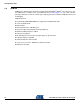
Figure 4-2. AT91SAM7L Block Diagram
For more information about the AT91SAM7L microcontroller, please refer to the AT91SAM7L-series
datasheet at www.atmel.com.
Backup Unit
User Peripherals
System Peripherals
SRAM
2KB (Backup)
4KB (Core)
ARM7TDMI
APB
Peripheral Bridge
AMBA System Bus
PWM
x4
SPI TWI
16-bit
Timer
x3
I/O
x80
RC OSC
2MHz
PIT
WDT
DBGU
PMC
AIC
RSTC
PLL
ADC
x4
Flash
64-128kB
ROM
FFPI
SAM-BA Boot
USART
USART
PDCPDC
PDC
PDC
PDC
1.8V
Voltage
Regulator
PIOA/B/C
Peripheral DMA
Controller: 11 channels
JTAG ICE
JTAG
Boundary Scan
Segment
LCD
Controller
40
segments
X
10
Terminals
BOD
RTC
POR
RC OSC
32kHz
XTAL
32kHz
LCD
Charge
Pump
LCD
Voltage
Regulator
PDC
Supply
Contr
IAP