AT91SAM7L-STK Rev. A Starter Kit ....................................................................................................................
1-2 6409A–ATARM–30-Jun-08 AT91SAM7L-STK Rev.
Table of Contents Section 1 Overview .................................................................................................................... 1-1 1.1 Scope................................................................................................................................. 1-1 1.2 Deliverables ...................................................................................................................... 1-1 1.3 The AT91SAM7L-STK Rev. A Starter Board .......................
Table of Contents (Continued) 6.1 Q1 Footprint Incorrect ........................................................................................................ 6-1 6.2 MAX3318 Control Pull-ups................................................................................................. 6-2 Section 7 Revision History ......................................................................................................... 7-1 ii 6409A–ATARM–30-Jun-08 AT91SAM7L-STK Rev.
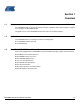
Section 1 Overview 1.1 Scope The AT91SAM7L-STK rev.A starter kit enables evaluation capabilities and code development of applications running on an AT91SAM7L64/128. This guide focuses on the AT91SAM7L-STK rev.A board as an evaluation platform. 1.2 Deliverables The AT91SAM7L-STK rev.A package contains the following items: 1.3 An AT91SAM7L-STK rev.A board Two AAA batteries The AT91SAM7L-STK Rev.
Section 2 Setting Up the AT91SAM7L-STK Rev. A Board 2.1 Electrostatic Warning The AT91SAM7L-STK rev.A starter board is shipped in a protective anti-static package. The board must not be subjected to high electrostatic potentials. A grounding strap or similar protective device should be worn when handling the board. Avoid touching the component pins or any other metallic element. 2.2 Requirements In order to set up the AT91SAM7L-STK rev.
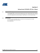
Setting Up the AT91SAM7L-STK Rev. A Board 2.3 Layout Figure 2-1. 2.4 AT91SAM7L-STK Rev. A Board Layout Powering Up the Board The AT91SAM7L-STK rev.A requires 3.0V (2.2V-3.6V) DC input. The power is supplied to the board via 2 AAA batteries or 3.0V VCC pads. 2.5 Getting Started Please refer to the AT91SAM product pages on the Atmel web site, for the most up-to-date information on getting started with the AT91SAM7L-STK rev.A. 2-2 6409A–ATARM–30-Jun-08 AT91SAM7L-STK Rev.
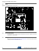
Setting Up the AT91SAM7L-STK Rev. A Board AT91SAM7L-STK Rev. A Block Diagram Figure 2-2. AT91SAM7L-STK Block Diagram Interfaces SHEET 2 '%*8 PC[0..29] 56 2.6 =,*%(( PC[0..29] Interfaces Processor AD[0..3] PA[0..25] PB[0..23] PC[0..29] SHEET 4 AD[0..3] PA[0..25] PB[0..23] PC[0..29] ERASE Processor LCD, KBD AD[0..3] PA[0..25] PB[0..23] PC[0..29] SHEET 3 AD[0..3] PA[0..25] PB[0..23] PC[0..29] ERASE LCD, KBD AT91SAM7L-STK Rev.
Section 3 Board Description 3.
Board Description • Debug Unit (DBGU) • • • • • • • • • • • • • • • • • • 3-2 6409A–ATARM–30-Jun-08 – Two-wire UART and Support for Debug Communication Channel interrupt, Programmable ICE Access Prevention Periodic Interval Timer (PIT) – 20-bit Programmable Counter plus 12-bit Interval Counter Windowed Watchdog (WDT) – 12-bit Key-protected Programmable Counter – Provides Reset or Interrupt Signals to the System – Counter may be Stopped While the Processor is in Debug State or in Idle Mode Real-t
Board Description 3.2 AT91SAM7L64/128 Block Diagram Figure 3-1. AT91SAM7L64/128 Block Diagram TDI TDO TMS TCK ICE JTAG SCAN Charge Pump ARM7TDMI Processor JTAGSEL LCD Voltage Regulator System Controller 2 MHz RCOSC TST CAPP1 CAPM1 CAPP2 CAPM2 VDDINLCD VDD3V6 VDDLCD VDDIO2 IRQ0-IRQ1 PIO FIQ 1.
Board Description 3.3 3.4 Memory 6 Kbytes of Internal single-cycle access High-speed SRAM 64/128 Kbytes of Internal single-cycle access High-speed Flash Clock Circuitry 3.5 3.6 3.7 3.8 Reset Circuitry Internal reset controller with a bi-directional reset pin External reset push button Shut Down controller Programmable shutdown and Wake-Up Wake-up push button.
Board Description 3.11 PIO Usage Table 3-1.
Board Description Table 3-2.
Board Description Table 3-3.
Section 4 Configuration 4.1 Configuration Straps Table 4-1 gives details of configuration straps on the AT91SAM7L-STK rev. A starter board and their default settings. Table 4-1.
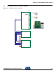
Section 5 Schematics This section contains the following schematics: Top Level Interfaces LCD, KBD Processor AT91SAM7L-STK Rev.
5 4 3 Interfaces 2 1 SHEET 2 D D PC[0..29] PC[0..29] C C Interfaces Processor AD[0..3] PA[0..25] PB[0..23] PC[0..29] SHEET 4 AD[0..3] PA[0..25] PB[0..23] PC[0..29] ERASE Processor B LCD, KBD AD[0..3] PA[0..25] PB[0..23] PC[0..29] SHEET 3 B AD[0..3] PA[0..25] PB[0..23] PC[0..29] ERASE LCD, KBD A A A REV AT91SAM7L-STK INIT EDIT MODIF. SCALE PP DES. 17MAR08 DATE 1/1 Top level This agreement is our property.
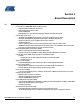
5 4 3 2 1 J1 PC[0..
5 4 3 2 1 BP1 PC[0..29] PB[0..23] 3-1437565-0 PC1 UP PC0 OK PC2 RIGHT PC4 LEFT PC3 DOWN PA[0..
5 4 3 2 1 PC[0..
Section 6 Errata 6.1 Q1 Footprint Incorrect Transistor Q1 is incorrectly connected. The schematic is right but the PCB connections of pins S and D are swapped => the protection diode is polarized forward (permanent current flow across the bridge) and the MOS is not operating properly (non accurate battery level measurement). Problem Fix/Workaround Remove Q1 in order to avoid the parasitic 150 µA battery drain.
Section 7 Revision History Doc Rev 6409A Comments Change Request Ref. First issue. AT91SAM7L-STK Rev.
Headquarters International Atmel Corporation 2325 Orchard Parkway San Jose, CA 95131 USA Tel: 1(408) 441-0311 Fax: 1(408) 487-2600 Atmel Asia Room 1219 Chinachem Golden Plaza 77 Mody Road Tsimshatsui East Kowloon Hong Kong Tel: (852) 2721-9778 Fax: (852) 2722-1369 Atmel Europe Le Krebs 8, Rue Jean-Pierre Timbaud BP 309 78054 Saint-Quentin-enYvelines Cedex France Tel: (33) 1-30-60-70-00 Fax: (33) 1-30-60-71-11 Atmel Japan 9F, Tonetsu Shinkawa Bldg.