
Specifications


6
6263A–ATARM–10-Oct-06
Application Note
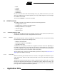
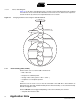
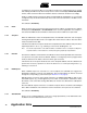
3.3.1.7 Device State Diagram
Figure 3-1 is the device state diagram (refer to chapter 9 of the USB specification 2.0), modified
to include the various methods described above. Note that since no method can suspend or
resume the device by software, the Suspended states are not shown.
Figure 3-1. Changing the Device State using the USB API Methods
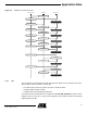
3.3.2 Event Handling (USB_Handler)
Several events can occur at the USB controller level:
• End of bus reset
• Reception of a SETUP packet
• Change of bus activity (active -> idle -> active ..)
• Completion of an endpoint operation
•Etc.
Whenever such an event occurs, it must be forwarded to the USB API to be handled in an
appropriate way. The USB_Handler method performs this functionality, so the controller interrupt
must be configured to call it.
Several callbacks can be triggered depending on the event notified by the controller:
• Suspend, when the bus is idle
Configured
Address
USB_SetConfiguration
Default
USB_SetAddress
USB_SetAddress
Powered
Attached
USB_Connect
USB_Attach
USB_Disconnect
USB_Init
USB_SetConfiguration
USB_Attach