AT91 USB Framework 1. Introduction This document describes a device-side USB framework developed for Atmel® AT91 ARM® Thumb® based microcontrollers. It enables rapid development of USB-compliant class drivers such as the Mass Storage Device class (MSD) or the Communication Device Class (CDC). Most microcontrollers of the AT91 family embed a USB controller. However, since there are several different controllers used in the devices, the framework provides a hardware layer abstraction.
3. Framework Description The framework is comprised of several components: • Standard USB structures • USB API – Structures – Methods • Callback API • Standard Request handler 3.
Application Note A pointer to an S_usb instance is needed to use all of the USB API methods. This pointer is passed as an argument to callbacks so they do not require direct access to it. The information stored in an S_usb object can be accessed using the following macros: • USB_GetEndpoint: returns a pointer to the specified endpoint • USB_GetSetup: returns a pointer to the last setup request received • USB_GetDriverInterface, USB_GetDriverID, USB_GetDriverPMC: see Section 3.2.2.
• Reset • Suspend • Resume • NewRequest • StartOfFrame Be sure to use the same order when declaring the S_usb_callbacks structure in your code. Since most callbacks have the same arguments, not every compiler will give an error message if two callbacks are inverted. This structure should be a constant to save RAM. 3.
Application Note This function triggers the Resume and the Suspend callbacks upon attachment/detachment. Those callbacks are used to put the device into low-power mode if needed. More information is given in Section 3.4.4 and Section 3.4.5 on page 10. Note that if the device is bus-powered, i.e., its only power source is VBus, then this function should be called once to power up the peripheral. Otherwise, it should be tied to a VBus monitoring routine.
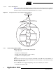
3.3.1.7 Device State Diagram Figure 3-1 is the device state diagram (refer to chapter 9 of the USB specification 2.0), modified to include the various methods described above. Note that since no method can suspend or resume the device by software, the Suspended states are not shown. Figure 3-1.
Application Note • Resume, when the bus becomes active again • Reset, when an end-of-bus reset is detected • NewRequest, when a setup packet is received on a control endpoint • StartOfFrame, every 1 ms (for full-speed controllers) or 125 µs (for high-speed controllers) More information about these callbacks and their expected behavior can be found in Section 3.4 on page 8. 3.3.3 Endpoint Behavior Modification The USB API offers three functions to control how an endpoint operates.
This function handles double-buffering, if it is supported by the USB controller and if it has been enabled for the endpoint. Do not forget that using double-buffering is mandatory for isochronous transactions. 3.3.4.2 USB_SendZLP0 Sending a zero-length packet (ZLP) on endpoint 0 is a common action, e.g., to acknowledge requests when no IN data is sent. This method is a redefinition of USB_Write that provides a simpler means of performing this kind of operation. 3.3.4.
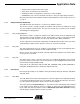
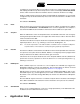
Application Note Figure 3-2. Callback Invocation Flowchart USB controller USB API Application USB_Init Initialization Callback: Init End of bus reset USB_Handler SETUP received Callback: Reset USB_Handler Bus idle Callback: NewRequest USB_Handler Bus activity Callback: Suspend USB_Handler Start of USB frame Callback: Resume USB_Handler Callback: StartOfFrame Cable disconnected Interrupt handler USB_Attach Callback: Suspend Cable connected Interrupt handler USB_Attach Callback: Resume 3.4.
If a PIO pin is connected to VBus, it is possible to monitor it by configuring the pin as an input and enabling the PIO interrupt. The interrupt service routine should simply call the USB_Attach function, which checks the Vbus line and either attaches or detaches the device accordingly. Finally, if an OS is being used, then the driver should probably be installed prior to use. Interrupt configuration may also be done differently. Please refer to the documentation of the OS for more information.
Application Note Because the start-of-frame interrupt puts some stress on the processor (since it is called a lot), it is only activated if the corresponding callback is defined. 3.5 Standard Request Handling Chapter 9 of the USB specification 2.0 defines a set of standard requests which have to be implemented by all devices. Since most class drivers treat those requests in the standard way, the USB framework provides a way to easily do that. 3.5.
3.5.1.4 Clear Feature, Set Feature & Get Status Several features of a device can either be activated or deactivated by the USB host: • Remote wakeup • Endpoint Halt state Three requests can be used to either set, clear or get the status of these two features: SET_FEATURE, CLEAR_FEATURE and GET_STATUS. The STD_RequestHandler method answers a Halt state operation by calling the USB_Halt method on the endpoint with the request. 3.5.
Application Note core_usb.h: USB API definitions core_udp.c: UDP controller driver methods Makefile: makefile used to build the project 4.2 Headers When programming your own application, most if not all the headers described in the file architecture of the framework must be included. However, since each header has its own dependencies, they must be included in a particular order. Here is the standard inclusion order: #include "core_common.h" #include "core_device.h" #include "core_board.
– Possible values: YES, NO. – Default: NO. • LEDS – Optional, enables the program to use the board LEDs to signal device activity. – Possible values: YES, NO. – Default: NO. • TRACES – Optional, enables the program to use the DBGU port to output debug traces. – Possible values: YES, NO.
Application Note Endpoints can be configured to have a specific number of FIFO banks (depending on the USB controller peripheral), each endpoint must be specified as either single- or dual-bank (see Section 3.2.3 on page 3). In the present case, endpoint 0 can only be a single-bank endpoint according to the UDP controller specification: // Endpoints static S_usb_endpoint pEndpoints[] = { // Control endpoint 0 USB_ENDPOINT_SINGLEBANK, }; 5.2.1.2 Callbacks A S_usb_callbacks (see Section 3.2.
// USB instance static const S_usb sUsb = { &sDefaultDriver, pEndpoints, 1, &sCallbacks, &sSetup }; Please refer to Section 3.2.1 on page 2 for more information about the S_usb structure. 5.2.2 Descriptors The USB specification 2.0 defines a set of descriptors used to give information about the device. Depending on the USB class implemented, different descriptors have to be used with varying values. In this example program, only a few descriptors are required.
Application Note 5.2.2.2 Configuration & Interface Descriptors When the configuration descriptor is requested by the host, via the GET_DESCRIPTOR command, the device must not only transmit this descriptor but also all the necessary interface and endpoint descriptors. In order to do that easily, a structure must be defined for holding all the information. This way, the data to send is contiguous, making the request much simpler to fulfill.
Again, those are very generic values. For the interface descriptor, most of them are zeroed. This is because this example does not implement any functionality other than doing the USB enumeration. 5.2.2.3 String Descriptors Only one structure is provided by the USB framework to declare string descriptors: for the language ID. This is because those descriptors have a variable size, and can most of the time be declared as a character array.
Application Note (char *) &sLanguageID, pManufacturer, pProduct, pSerial }; The actual descriptors list can then be instantiated: // List of descriptors used by the device static S_std_descriptors sDescriptors = { &sDeviceDescriptor, (S_usb_configuration_descriptor *) &sConfigurationDescriptor, pStringDescriptors, 0 // List of endpoint descriptors (excluding endpoint 0), not used }; The core configuration descriptor, which is actually made up of the configuration descriptor and the first interface descrip
do that, an interrupt must be programmed when the status of VBus changes. The ISR should call the USB_Attach function as follows: void ISR_VBus() { USB_Attach(&sUsb); // Acknowledge the interrupt by making a dummy write in ISR AT91C_PIO_VBUS->PIO_ISR = 0; } How to register both ISRs is detailed in Section 5.4. 5.4 Callbacks A typical application based on this USB framework needs to instantiate most of the callbacks available. This section describes how to do that for a simple enumeration program. 5.4.
Application Note 5.4.2 Suspend & Resume The Suspend callback is used by the USB API to notify the device that it should enter low-power mode if required. Since a method is provided to perform this operation in the core_device.c file, it can be called here: static void CBK_Suspend(const S_usb *pUsb) { DEV_Suspend(); } The Resume callback has to perform the reverse operation, which can be done by calling the DEV_Resume method.
6. Revision History Table 6-1. Document Ref. Comments 6263 First issue 22 Change Request Ref.
Atmel Corporation 2325 Orchard Parkway San Jose, CA 95131, USA Tel: 1(408) 441-0311 Fax: 1(408) 487-2600 Regional Headquarters Europe Atmel Sarl Route des Arsenaux 41 Case Postale 80 CH-1705 Fribourg Switzerland Tel: (41) 26-426-5555 Fax: (41) 26-426-5500 Asia Room 1219 Chinachem Golden Plaza 77 Mody Road Tsimshatsui East Kowloon Hong Kong Tel: (852) 2721-9778 Fax: (852) 2722-1369 Japan 9F, Tonetsu Shinkawa Bldg.