
Datasheet


16
1919C–MICRO–3/05
AT89S52
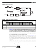
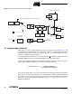
Figure 11-1. Timer 2 in Baud Rate Generator Mode
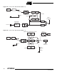
12. Programmable Clock Out
A 50% duty cycle clock can be programmed to come out on P1.0, as shown in Figure 12-1. This
pin, besides being a regular I/O pin, has two alternate functions. It can be programmed to input
the external clock for Timer/Counter 2 or to output a 50% duty cycle clock ranging from 61 Hz to
4 MHz (for a 16-MHz operating frequency).
To configure the Timer/Counter 2 as a clock generator, bit C/T2
(T2CON.1) must be cleared and
bit T2OE (T2MOD.1) must be set. Bit TR2 (T2CON.2) starts and stops the timer.
The clock-out frequency depends on the oscillator frequency and the reload value of Timer 2
capture registers (RCAP2H, RCAP2L), as shown in the following equation.
In the clock-out mode, Timer 2 roll-overs will not generate an interrupt. This behavior is similar to
when Timer 2 is used as a baud-rate generator. It is possible to use Timer 2 as a baud-rate gen-
erator and a clock generator simultaneously. Note, however, that the baud-rate and clock-out
frequencies cannot be determined independently from one another since they both use
RCAP2H and RCAP2L.
OSC
SMOD1
RCLK
TCLK
Rx
CLOCK
Tx
CLOCK
T2EX PIN
T2 PIN
TR2
CONTROL
"1"
"1"
"1"
"0"
"0"
"0"
TIMER 1 OVERFLOW
NOTE: OSC. FREQ. IS DIVIDED BY 2, NOT 12
TIMER 2
INTERRUPT
2
2
16
16
RCAP2LRCAP2H
TH2 TL2
C/T2 = 0
C/T2 = 1
EXF2
CONTROL
TRANSITION
DETECTOR
EXEN2
÷
÷
÷
÷
Clock-Out Frequency
Oscillator Frequency
4 x [65536-(RCAP2H,RCAP2L)]
------------------------------------------------------------------------------------ -=