
User`s guide


Using the AT85DVK-07 Board
AT85DVK-07 Development Board User Guide 2-17
4391B–MP3–07/07
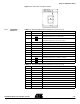
Table 2-16. Audio DAC Extension Connector (J9)
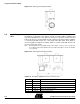
2.9.1 Headphone Amp
Configuration
In very-low voltage application, the on-chip headphone amplifier is not able to drive the
headphone. In this case an external amplifier must be configured as detailed in Figure
2-17.
Note:
On-board
or
on-chip
headphone amplifier option must also be configured by user in the
audio firmware driver (for further information, refer to the firmware user’s manual).
Figure 2-17. Headphone Amplifier Configuration (bottom view)
7 AMP_OC Common reference amplifier output
8 AMP_OL Amplifier right channel output
9 AVSS 0V analog supply reference
10 NC
Pin Number Pin Name Pin Description
1 VDD IOVDD power supply 1.8V or 3V depending on the power configuration
2 DAC_I0 DAC control bit 0
3 DAC_I1 DAC control bit 1
4 DAC_I2 DAC control bit 2
5 DAC_I3 DAC control bit 3
6 DAC_nRST Active low DAC reset signal
7 DAC_OCLK DAC oversampling clock
8 DAC_DCLK DAC data clock
9 DAC_DDAT DAC data line
10 DAC_DSEL DAC channel select line
11 VSS 0V digital supply reference
12 VSS 0V digital supply reference
13 DAC_OR DAC left channel output
14 DAC_OC Common reference DAC output
15 DAC_OL DAC right channel output
16 AVSS 0V analog supply reference
17 AVSS 0V analog supply reference
Pin Number Pin Name Pin Description
Low Voltage Application Very Low Voltage Application
MIC
(on-chip amplifier) (on-board amplifier)
SE2
SE1
SE19
SE18
MIC
SE2
SE1
SE19
SE18
SE51
SE51