
User`s guide


Using the AT85DVK-07 Board
2-14 AT85DVK-07 Development Board User Guide
4391B–MP3–07/07
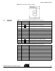
Figure 2-12. Nand Flash Daughter Board Plug-In
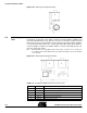
2.6.2 On-Board Nand
Flash Configuration
In case nand flash memory is soldered on board (user’s responsibility) a hardware con-
figuration must be applied (see Figure 2-13) to avoid any conflict with a nand flash
daughter board that may be plugged-in.
When no nand flash memory is soldered solder straps may be left opened.
Figure 2-13. Nand Flash Configuration (bottom view)
2.7 MMC/SD Unit
The MMC/SD unit consists in a single card socket that allows direct plug-in of MMC, RS-
MMC and SD cards.
11 NFD1 Data Bit 1
12 NFD0 Data Bit 0
13 VSS 0V digital supply reference
Pin Number Pin Name Pin Description
Nand Flash
Index
J14
J13
SE7
SE17
On-board Nand Flash not used On-board Nand Flash used
SE7
SE17