
User`s guide


Using the AT85DVK-07 Board
AT85DVK-07 Development Board User Guide 2-9
4391B–MP3–07/07
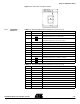
Figure 2-6. Low Voltage Application Power Configuration
Notes: 1. Option to allow power key-press detection by the AT85C51SND3Bx.
2. Option to allow battery voltage monitoring by the AT85C51SND3Bx.
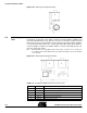
2.2.5 External DC-DC
Replacement
In order to allow developers to validate other external DC-DC power supply solution, two
extension connectors J19 and J22 (see Table 2-6 and Table 2-7) are provided as option
to plug a daughter board featuring an external 3V low voltage DC-DC.
In such configuration the board must be configured in “Low Voltage” mode and SE38
along with SE56 must be open.
Table 2-6. External DC-DC Extension Connector (J19)
Table 2-7. External DC-DC Extension Connector (J22)
2.3 Microcontroller
Unit
The Microcontroller unit consists in the AT85C51SND3Bx component in LQFP100 pin
package including its 12 MHz oscillator and the reset (RST) and in system programming
(ISP) push-buttons.
SE35
AAA Battery
SE33
SE32
SE34
SE56
SE57
(1)
SE58
L5
Socket
Bottom View Top View
SE38
SE37
(2)
J20
Pin Number Pin Name Pin Description
1 VBAT Direct battery supply voltage
2 EXTDC Battery supply voltage (SE38 ON)
3 P3.4/EXTDC_ON Asserted low permanent power-on signal
4 SW_ON Active low power-on switch
Pin Number Pin Name Pin Description
1 VBUS USB +5V supply voltage
2 HVDD 3V supply voltage
3 LVDD 1.8V supply voltage
4 VSS 0V digital supply reference