
User`s guide


Using the AT85DVK-07 Board
2-8 AT85DVK-07 Development Board User Guide
4391B–MP3–07/07
2.2.4 Power Configuration The power configuration is done through a set of solder straps. By default, the
AT85DVK-07 Board is delivered configured in “Low Voltage 3V application” meaning all
external components (LCD, NF, MMC…) are powered at 3V.
Note: “Very Low Voltage 1.8V application” uses the on-chip 1.8V DC-DC of the
AT85C51SND3Bx while “Low Voltage 3V application” uses the external on-board DC-
DC.
Table 2-5. Power Configuration
Notes: 1. Option to allow battery voltage monitoring by the AT85C51SND3Bx.
2. Option to allow power key-press detection by the AT85C51SND3Bx.
3. Remove this connection when using a daughter board DC-DC extension.
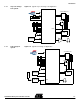
Figure 2-5. Very Low Voltage Application Power Configuration
Solder Strap
Very Low Voltage
Application
Low Voltage
Application Comment
SE32 X
VDD selection amongst HVDD or LVDD
SE34 X
SE33 X
AVDD2 selection amongst HVDD or LVDD
SE35 X
SE37 X X
(1)
Internal / External DC-DC V
BAT
Selection
SE38 X
(3)
SE56 X
(3)
On-board DC-DC output insulation
SE57 X X
(2)
Power-on switch routing
SE58 X
SE35
AAA Battery
SE33
SE32
SE34
SE56
SE57
SE58
L5
Socket
Bottom View Top View
SE38
SE37
J20