
User guide

AVR1607
9
8311A-AVR-07/10
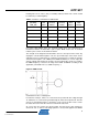
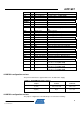
PA3 98 V_conditioned = V / 6 (Not used)
PA4 99 W_conditioned = W / 6 (Not used)
PA5 100 Vn_conditioned Neutral voltage / 34 (Not used)
PA6 1 Vm
(Not used)
PA7 2 W_cond_neg W Reference for zero-crossing (Not used)
PORTB
PB0 5 Speed_ref Speed Potentiometer (MC303)
PB1 6
PB2 7 Current_reference = AVCC / 34
PB3 8 Shunt_pos 0.05 ohm shunt voltage ( = motor current /
20)
PB4 9 Shunt_neg GND of Vmotor
PB5 10 Shunt_U = Shunt_pos (not used)
PB6 11 Shunt_V = Shunt_pos (not used)
PB7 12 Shunt_W = Shunt_pos (not used)
PORTC
PC0 15 UL Drives T1 power transistor of MC300
PC1 16 UH Drives T2 power transistor of MC300
PC2 17 VL Drives T3 power transistor of MC300
PC3 18 VH Drives T4 power transistor of MC300
PC4 19 WL Drives T5 power transistor of MC300
PC5 20 WH Drives T6 power transistor of MC300
PORT E
PE0 H1 Hall sensor 1 signal
PE1 H2 Hall sensor 2 signal
PE2 H3 Hall sensor 3 signal
PE4 Fault_overcurrent External comparator ( MC303)output
PE5 Fault_IPM
(Not used)
PORT H
PHO ZC_U Zero crossing external comparator output :
sensorless mode (Not used)
PH1 ZC_V Zero crossing external comparator output :
sensorless mode (Not used)
PH2 ZC_W Zero crossing external comparator output :
sensorless mode (Not used)
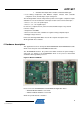
4.2 MC300 configuration and use
The power board must be supplied with a 12V, 2A, DC Power Supply.
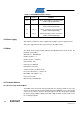
Table 1-3. ATAVRMC300 jumper settings
Jumper Position Comment
J1(VHa) Pin1 & 2 shorted VHa = +5V
J2(VCC) Open Vcc = +5V
4.3 MC303 configuration and use
The jumpers configuration of the MC303 processor board is following :