
User guide

8
AVR1607
8311A-AVR-07/10
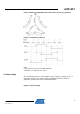
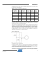
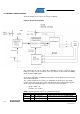
4.1 Hardware implementation
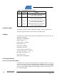
The block diagram of the sensor closed loop is following :
Figure 8. System block diagram
The outputs UH, UL, VH, VL, WH & WL of AVR303 are used to control the power
bridge (see Table 1-2). As previously seen, they depend on the Timer0 and AWEX
whi
ch generates PWM signals.
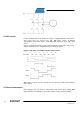
An external comparator on MC303 board provides a fault signal (Fault_overcurrent)
connected to PE4 input.:
The compared inputs are the shunt_pos and AVCC/ 34. Shunt_pos is the voltage
monitored across the 0.05 ohm resistor, and equals the motor current divided per 20.
So the comparator output will toggle as soon as motor current Im will be :
Im /20 > AVCC / 34
So limit is : Im > 2.94 A
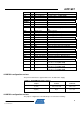
Table 1-2. Microcontroller I/O ports use (TQFP100 package)
PORT A
PA0 95 U_cond_neg U Reference for zero-crossing (Not used)
PA1 96 V_cond_neg V Reference for zero-crossing (Not used)
PA2 97 U_conditioned = U / 6 (Not used)