
User guide

AVR1607
7
8311A-AVR-07/10
o 8x4 differential inputs with selectable 1/2/4/8/16/32/64x gain
• Four Analog Comparators with Window compare function, with selectable
comparison levels, and interrupts on pin change I/Os.
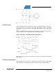
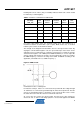
The ATxmega128A1 includes independent positive and negative comparator inputs
available for over-current detection. The Input selection can be achieved from pins :
- Pins 0, 1, 2, 3, 4, 5, 6 for positive input
- Pins 0, 1, 3, 5, 7 for negative input
Its reference (comparison level) can be fixed via the DAC output or any external
reference voltage :
– Output from 12-bit DAC
– 64-level scaler of the VCC, available on negative analog comparator input
– Bandgap voltage reference
Refer to the ATxmega128A1 Data sheet for the complete description of the
ATxmega128A1 microcontroller
.
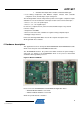
4 Hardware description
This application has been developed with ATAVRMC300 and ATAVRMC303 boards
which are the two parts of the ATAVRMC323 Starter kit..
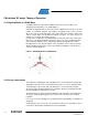
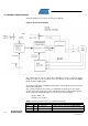
The ATAVRMC300 board is the power board which embeds the power bridge is
connected (see below) to the ATAVRMC303 which is the processor board built
around the ATxmega128A1 processor.
Figure 7. MC303 and MC300
Please refer to the ATAVRMC300 and ATAVRMC303 Application Notes :
- AVR430: MC300 Hardware User Guide
- AVR1014: MC303 Hardware User Guide
which also provide boards schematics.