
User guide

6
AVR1607
8311A-AVR-07/10
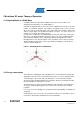
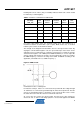
motor. Then Phase U is unpowered and Phase W is connected to the positive DC
bus, resulting in a new stator flux vector ‘Step 4’.
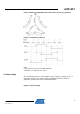
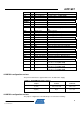
Following the commutation schematic Figure 5 and Table 1-1, we get six different
stator flux vectors
corresponding to the six commutation steps. These six steps
provide one electrical revolution.
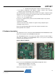
3 ATxmega128A1 microcontroller
Based on the high performance AVR 8-bit RISC architecture, the ATxmega128A1
integrates all of the basic peripherals necessary to satisfy the needs of complex
algorithms.
The ATxmega128A1 has all necessary resources to provide an integrated solution to
control BLDC motors in their system environments.
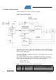
3.1 Timer/Counters
ATxmega128A1 provides 16-bit timers/counters with :
Four Compare or Capture (CC) Channels in Timer/Counter 0
Two Compare or Capture (CC) Channels in Timer/Counter 1
To generate PWM frequency, this Application Note uses three compare channels
(A,B,C) of Timer0 and the Advanced Waveform Extension (AWEX) additional feature
to Timer 0. AWEX function is available for ports C and E (Port C is used in this
Application Note).
The benefits of AWEX features for motor control are :
• Complementary outputs from each Capture channel
• Four Dead Time Insertion (DTI) which avoid cross conduction
•
Separate High and Low Side Dead-Time Setting
• Double Buffered Dead-Time
• Event Controlled Fault Protection
• Single Channel Multiple Output Operation
• Double Buffered Pattern Generation
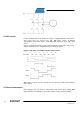
The output pairs go through a Dead-Time Insertion (DTI) unit that enables generation
of the non-inverted Low Side (LS) and inverted High Side (HS) of the WG output with
dead time insertion between LS and HS switching. The DTI output will override the
normal port value according to the port override setting.
The Fault Protection unit is connected to the Event System. This enables any event to
trigger a fault condition that will disable the AWEX output. Several event channels can
be used to trigger fault on several different conditions.
3.2 Analog features
ATxmaga128A1 integrates also analog blocks like :
• Two Eight-channel, 12-bit, 2 Msps Analog to Digital Converters, with
programmable gain options.
The inputs per ADC are :
o 8 single ended inputs