
User guide

AVR1607
5
8311A-AVR-07/10
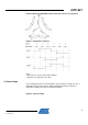
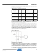
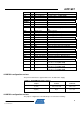
Reading hall sensors values (HS_xxx variable) indicates which new scheme should
be switched.(see following table)
Table 1-1. Switches commutation for CW rotation
Hall Sensors Value
(H1 H2 H3)
= HS_xxx
Hall
States
Previous
Phases
Previous
scheme
Next
Phases
Next
scheme
110 3 V-W T3 ; T6 U-W T1 ; T6
100 1 U-W T1 ; T6 U-V T1 ; T4
101 5 U-V T1 ; T4 W-V T5 ; T4
001 4 W-V T5 ; T4 W-U T5 ; T2
011 6 W-U T5 ; T2 V-U T3 ; T2
010 2 V-U T3 ; T2 V-W T3 ; T6
For motors with multiple poles the electrical rotation does not correspond to a
mechanical rotation. A motor with n pair of poles BLDC motor uses n electrical
rotation cycles to have one mechanical rotation.
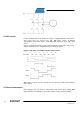
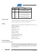
The strength of the magnetic field determines the force and speed of the motor. By
varying the current flow through the coils, the speed and torque of the motor can be
adjusted. The most common way to control the current flow is to control the average
current flow through the coils. PWM (Pulse Width Modulation) is used to adjust the
average voltage and thereby the average current, inducing the speed. For example,
the PWM frequency selected is the range from 10kHz to 200kHz according to the
application (commutation losses, audible frequency...).
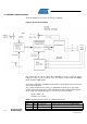
Figure 6. PWM scheme
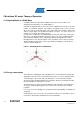
Commutation creates a rotating field.
For instance at Step 5, Phase U is connected to the positive DC bus voltage through
T1 and Phase V is connected to ground through T4, Phase W is unpowered. Two flux
vectors are generated by phase U and phase V The sum of the two vectors creates
the stator flux vector. Then the rotor tries to follow this stator flux.
As soon as the rotor reaches the given position, the hall sensors state changes its
value from “101” to “001” a new voltage pattern is selected and applied to the BLDC