
User guide

4
AVR1607
8311A-AVR-07/10
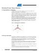
2.4 Hall sensors
For the estimation of the rotor position, the motor is equipped with three hall sensors.
These hall sensors are placed every 120°. With these sensors, 6 different
commutations are possible. Phase commutation will depend on these hall sensor
values.
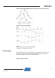
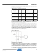
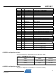
Figure 5 shows the three Hall sensors signals H1,H2,H3 as motor turns using sensor
control. Hall states are the combination result of H1,H2,H3 signals.
Figure 5. Hall states versus Motor leads in Sensor mode
With a motor of n pairs of poles, the hall sensors frequency is n times faster than the
motor rotation.
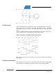
2.5 Phase Commutations
Power supply to the coils must be changed when hall sensor values change. With
right synchronized commutations, the torque remains nearly constant and high.