
User guide

AVR1607
3
8311A-AVR-07/10
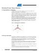
Figure 2. Model of a BLDC Motor with current flows versus rotor positions
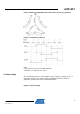
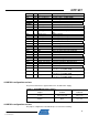
Figure 3. Commutation sequence
Notes :
- Open phase is the one shown with dotted line.
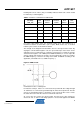
- Hall states are detailed in 2.4 section
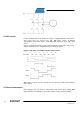
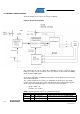
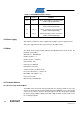
2.3 Power Stage
The commutation pattern is controlled with a 3-phase bridge (see Figure 4). The 3
half bridges have 6 power switches (IGBT or MOSFET transistors) which are
switched according to the defined commutation pattern.
Figure 4. 3-phases bridge