
User guide

2
AVR1607
8311A-AVR-07/10
2 Brushless DC motor Theory of Operation
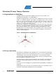
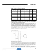
2.1 Simplified Model of a BLDC Motor
A simplified model of a three phases BLDC motor stator consists of three coils
arranged in three directions U, V and W (Figure 1).
A perm
anent magnet forms the rotor. The rotor in a BLDC motor consists of an even
number of permanent magnets. The number of magnetic poles in the rotor also
affects the step size and torque ripple of the motor. More poles provide smaller steps
and less torque ripple. The permanent magnets go from 1 to 5 pairs of poles. In
certain cases it can go up to 8 pairs of poles.
Here the rotor is outlined as a bar magnet with its rotary axis at the intersection of the
three axes U, V, W perpendicular to the plane of these axis. The orientation/position
of the permanent magnet can be controlled by driving a configuration of currents
through the three coils. The bar magnet comes to position sector 1 when a current is
driven from W through V and it comes to the following orientation (sector 2) when a
current is driven from W to U.
Figure 1. Simplified Model of a BLDC Motor
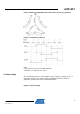
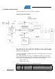
2.2 Six-step commutation
The method for energizing the motor windings in the sensor method described in this
application note is the six-step commutation. Each step, or sector, is equivalent to 60
electrical degrees. Six sectors make up 360 degrees, or one electrical revolution.
The arrows in the winding diagram Figure 2 show the direction current flows through
the motor wi
ndings in each of the six sectors.
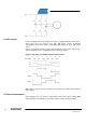
The graph (Figure 3) shows the voltage applied at each lead of the motor during the
six se
ctors. Sequencing through these six sectors moves the motor one electrical
revolution.
For every sector, two windings are energized and the third winding is floating (not
energized).
Connecting the coils to the power and neutral bus induces the current flow. This is
referred to as trapezoidal commutation or block commutation.