
User guide

14
AVR1607
8311A-AVR-07/10
duty_cycle = mc_control_current(mc_get_potentiometer_value())
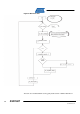
5.4 Commutation
The phase commutation has to be achieved according to the 3 Hall sensors.
Commutation between steps is achieved when a rising or falling edge occurs on one
of the 3 Hall sensor signals.
Hall sensor signals H1/H2/H3 are connected to PE0/PE1/PE2 which are configured
as interrupt sources.
(Another solution could be using internal comparators to generate interrupts.)
Port Interrupt 0 Mask is defined as :
sfrb PORTE_INT0MASK = 0x068A
Are also defined :
#define PORTE_INT0MASK PORTE.INT0MASK
PORTE.INT0MASK = (PIN0_bm | PIN1_bm | PIN2_bm);
This means that PORTE_INT0_vect (HALL-A()) is executed if any of the three Hall
senor signal is changing.
This interrupt vector executes :
• The transistor commutation according to the HALL_SENSOR_VALUE :
HALL_SENSOR_VALUE is the value of the 3 Hall sensor bits = PORTE.IN & 0x07
The commutation is achieved by the function :
mc_switch_commutation(HALL_SENSOR_VALUE)
• and estimation of speed on Rising edge of H1 (Hall A) sensor. This means the
speed is evaluated one time per electrical cycle.
5.4.1 mc_switch_commutation()
This fun
ction achieves two operations:
• First,the update of the duty-cycle, thanks to function
:mc_duty_cycle(mc_get_Duty_Cycle())
This is achieved with the update of the Output new compare value of the Timer:
TC_SetCompareA( &TCC0, level ); which updates CCABUF register with new
compare value
TC_SetCompareB( &TCC0, level );
TC_SetCompareC( &TCC0, level );
The dead time insertion is achieved with ConfigDTI() function which configures a
dead Time both sides equal to 3.