
User guide
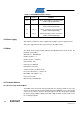

AVR1607
13
8311A-AVR-07/10
5.2 INIT : Initialisation functions
The initialization functions are following
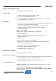
5.2.1 clock_init()
•
Oscillator : 32MHz RC oscillator and OSC oscillator
• PLL : clock source=32MHz and factor =16
• Prescalers: PSADIV=1 and PSB and PSCDIV=2 : means clk_
PE R4
= 128MHz,
clk_
PE R2
= 64MHz and clk_
PE R
= 32MHz
5.2.2 mc_init()
•
Port C : pins 0 to 5 are in output mode and clear (DIRSET and OUTCLR=1) are
the outputs connected to transistor power bridge
• Port E : The input pull up are activated to connect the Hall sensor signals
• External Interrupts are defined on Port E Pins0/1/2 (Hall signals)
• Timer 0 configuration is :
Clock prescaler /4 (8MHz)
PWM_Init (255) configures a PWM frequency = 15686 kHz
• Timer1 configuration is :
No Clock prescaler and period=8000 produces a g_tick each 1.024 ms
• ADCB configuration is :
- calibration/offset
- signed conversion mode and 12 bit resolution.
- ADC prescaler to a Sample rate of CPUFREQ/16. Allow time for storing data. */
- Set reference voltage to VCC-0.6 V
- Setup channel 0 to have single ended input and gain=1
- Set input to the channels in ADC B to be PIN 0
- Enable ADC B with free running mode
5.3 Regulation functions
The main loop functions are following.
5.3.1 mci_set_motor_speed ()
This fun
ction updates the speed setpoint according to the potentiometer adjustment
or the speed command received on serial transmission.
mc_get_potentiometer_value() returns mc_potentiometer_value
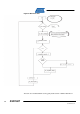
5.3.2 mc_regulation_loop() :
The duty_cy
cle variable controls the PWM generator. This variable is the result of
following functions :
in Open loop mode : duty_cycle = mc_get_motor_speed()
in Speed loop mode : duty_cycle = mc_control_speed(mc_get_motor_speed())
in Current loop mode :