
User Manual


Atmel AT03911: REB233CBB Module – User Manual [APPLICATION NOTE]
42156BWIRELESS02/2014
8
7. Firmware description
7.1 Range measurement
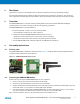
The REB233CBB Module is pre-flashed with the RF performance test suite featuring a range measurement application.
Each module operates in a standalone manner, and is able to transmit or receive data frames. A successful transmit or
receive operation is indicated by a blinking LED.
7.1.1 Power up the modules
Apply power to both modules by switching on the power switch. In consequence of, a module runs a power-on check
and indicates the successful completion by switching on the second of the three LEDs.
7.1.2 Run range measurement application
Select one of the REB233CBB Module and press pushbutton T1 to start the range measurement application.
First, the module initiates a connection and configuration procedure by sending broadcast frames and waiting for a
response from the second module. After successful configuration, the module turns on LED-D1 indicating this status.
The initiator starts transmitting data frames. Each data frame transmission is indicated by blinking the TX status LED-
D2. A successful data frame reception on the second node is indicated by blinking the RX status LED-D3. The frame
transmit repetition rate is fixed to ensure FCC compliance; the repetition rate cannot be changed.
The RX status LED stops blinking if no data frames are received, such as when, for example, the node has left the
communication range. Data frame transmission can be stopped by pressing T1 once more on the node transmitting
frames.
The REB233CBB Modules are able to transmit and receive simultaneously. Pressing pushbutton T1 on both nodes
initiates each node to transmit frames. Operating modes are indicated as: LED-D1 a successful start-up, LED-D2 in
transmit and LED-D3 in receive mode.
Note: The node configuration gets lost when resetting or switching off the radio modules power supply; to restart, a reset or
power cycle is required for both REB233CBB Modules before pressing T1 on one (or both) REB233CBB Module(s).
7.2 Packet error rate measurement
The RF performance test suite features a packet error rate measurement (as defined by IEEE802.15.4), and allows to
explore various radio transceiver features, radio transceiver registers, and performance by tuning with customized
configurations. For this application, at least one REB233CBB Module needs to be connected to a PC.
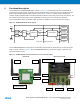
7.2.1 Module preparation
1. Prepare REB233CBB Modules as described in Chapter 4.2.
2. Make sure that the power switch on both modules is in the off position.
3. Plug an USB level-shifter into a free USB port on your host-PC. Interconnect
this adapter and one of the REB233CBB Modules via the 6-pin ribbon cable
so that it fits the notch on the adapter and the colored stripe of the ribbon
cable connects to pin 1 of the header USARTD0.