
User Manual


Atmel AT03911: REB233CBB Module – User Manual [APPLICATION NOTE]
42156BWIRELESS02/2014
6
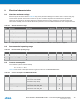
ATxmega256A3
Header USARTD0
Description
RESET (57)
RESET (5)
MCU reset
VTG (2)
Operating voltage
GND (6)
Ground
Synchronous operation is not supported.
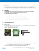
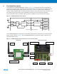
PC connectivity can be easily achieved by using a serial to USB level shifter stick [8] as shown in Figure 5-3.
Figure 5-3. USB level shifter stick.
5.8 ID EEPROM
The REB233CBB Module identifies the Radio PCB by checking the correct content of the Radio PCB identification (ID)
EEPROM, which handles information about the Radio PCB, the node MAC address and production calibration values.
This ensures no other Radio PCB type can be used in conjunction with the delivered Microcontroller PCB and firmware.
The firmware running on the Microcontroller PCB checks the correct content of the Radio PCB ID-EEPROM before
continuing with any radio operation. In case of wrong or unexpected content of the Radio PCB ID-EEPROM the
operation is stopped which is indicated by LEDs D1…D2 blinking.
Table 5-3 shows a detailed description of the Radio PCB ID-EEPROM data structure.
Table 5-3. ID EEPROM mapping.
Address
Name
Type
Description
0x00
MAC address
uint64
MAC address for the 802.15.4 node, little endian byte order
0x08
Serial number
uint64
Board serial number, little endian byte order
0x10
Board family
uint8
Internal board family identifier
0x11
Revision
uint8[3]
Board revision number ##.##.##
0x14
Feature
uint8
Board features, coded into seven bits
7
Reserved
6
Reserved
5
External LNA
4
External PA
3
Reserved
2
Diversity
1
Antenna
0
SMA connector
0x15
Cal OSC 16MHz
uint8
RF233 XTAL calibration value, register XTAL_TRIM
0x16
Cal RC 3.6V
uint8
Atmel ATxmega256A3 internal RC oscillator calibration value @ 3.6V
0x17
Cal RC 2.0V
uInt8
Atmel ATxmega256A3 internal RC oscillator calibration value @ 2.0V